Information fuel-injection pump
BOSCH
9 410 611 009
9410611009
ZEXEL
103066-0141
1030660141
Rating:
Scheme ###:
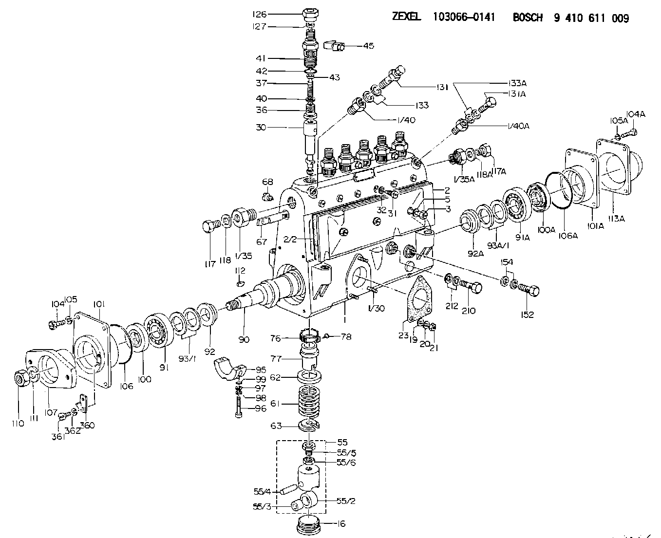
| 1. | [1] | 133050-8920 | PUMP HOUSING |
| 1/30. | [3] | 029040-6020 | STUD |
| 1/35. | [1] | 132400-0900 | ADAPTOR |
| 1/35A. | [1] | 132400-0900 | ADAPTOR |
| 1/40. | [1] | 131423-0200 | ADAPTOR |
| 1/40A. | [1] | 131002-2000 | ADAPTOR |
| 2. | [1] | 133010-6920 | COVER |
| 2/2. | [1] | 133011-0100 | GASKET |
| 3. | [3] | 133017-0900 | FLAT-HEAD SCREW |
| 5. | [3] | 029340-8010 | GASKET D12&8T1.00 |
| 16. | [6] | 133034-0400 | CAPSULE |
| 19. | [3] | 029300-6030 | PLAIN WASHER D11&6.4T0.5 |
| 20. | [3] | 014110-6410 | LOCKING WASHER |
| 21. | [3] | 013020-6020 | UNION NUT M6P1H5 |
| 23. | [1] | 133041-0400 | GASKET |
| 30. | [6] | 133151-6820 | PLUNGER-AND-BARREL ASSY |
| 31. | [6] | 133106-0100 | CAPSULE |
| 32. | [6] | 029330-8110 | GASKET D13&8.2T1.5 |
| 36. | [6] | 133110-2520 | DELIVERY-VALVE ASSEMBLY |
| 37. | [6] | 131112-2300 | COILED SPRING |
| 40. | [6] | 134115-0100 | GASKET |
| 41. | [6] | 133116-3200 | FITTING |
| 42. | [6] | 029632-5030 | O-RING |
| 43. | [6] | 131117-2100 | FILLER PIECE |
| 45. | [3] | 133122-1420 | PLATE |
| 55. | [6] | 133200-1320 | TAPPET |
| 55/2. | [1] | 133204-0700 | ROLLER |
| 55/3. | [1] | 133205-0200 | BUSHING |
| 55/4. | [1] | 133203-0200 | BEARING PIN |
| 55/5. | [1] | 133202-0100 | HEXAGON SCREW |
| 55/6. | [1] | 133201-0101 | UNION NUT |
| 61. | [6] | 133215-0600 | COMPRESSION SPRING |
| 62. | [6] | 133216-0100 | SLOTTED WASHER |
| 63. | [6] | 133217-0300 | SLOTTED WASHER |
| 67. | [1] | 133256-2800 | CONTROL RACK |
| 68. | [1] | 132226-0400 | FLAT-HEAD SCREW |
| 76. | [6] | 133240-0100 | PINION |
| 77. | [6] | 133241-0200 | CONTROL SLEEVE |
| 78. | [6] | 131242-0100 | FLAT-HEAD SCREW |
| 90. | [1] | 133370-1800 | CAMSHAFT |
| 91. | [1] | 016650-3030 | BEARING PLATE |
| 91A. | [1] | 016650-3030 | BEARING PLATE |
| 92. | [1] | 133302-0100 | SPACER RING |
| 92A. | [1] | 133302-0100 | SPACER RING |
| 93/1. | [0] | 029312-6010 | SHIM D40&26T0.1 |
| 93/1. | [0] | 029312-6020 | SHIM D40&26T0.12 |
| 93/1. | [0] | 029312-6030 | SHIM D40&26T0.14 |
| 93/1. | [0] | 029312-6040 | SHIM D40&26T0.16 |
| 93/1. | [0] | 029312-6050 | SHIM D40&26T0.18 |
| 93/1. | [0] | 029312-6060 | SHIM D40&26T0.5 |
| 93A/1. | [0] | 029312-6010 | SHIM D40&26T0.1 |
| 93A/1. | [0] | 029312-6020 | SHIM D40&26T0.12 |
| 93A/1. | [0] | 029312-6030 | SHIM D40&26T0.14 |
| 93A/1. | [0] | 029312-6040 | SHIM D40&26T0.16 |
| 93A/1. | [0] | 029312-6050 | SHIM D40&26T0.18 |
| 93A/1. | [0] | 029312-6060 | SHIM D40&26T0.5 |
| 95. | [1] | 133305-0800 | BEARING SHELL |
| 96. | [2] | 020608-4040 | HEX-SOCKET-HEAD CAP SCREW |
| 97. | [2] | 023500-8120 | PLAIN WASHER |
| 98. | [2] | 023650-8310 | LOCKING WASHER |
| 99. | [2] | 029630-9020 | O-RING |
| 100. | [1] | 029622-5010 | PACKING RING |
| 100A. | [1] | 029622-5010 | PACKING RING |
| 101. | [1] | 133316-4401 | COVER |
| 101A. | [1] | 133316-1300 | COVER |
| 104. | [4] | 029010-8020 | BLEEDER SCREW |
| 104A. | [4] | 021008-2520 | FLAT-HEAD SCREW |
| 105. | [4] | 014110-8410 | LOCKING WASHER |
| 105A. | [4] | 014110-8410 | LOCKING WASHER |
| 106. | [1] | 029637-2000 | O-RING |
| 106A. | [1] | 029637-2000 | O-RING |
| 107. | [1] | 156612-6300 | COUPLING PLATE |
| 110. | [1] | 029201-8040 | UNION NUT |
| 111. | [1] | 014111-8410 | LOCKING WASHER |
| 112. | [1] | 025805-1910 | WOODRUFF KEY |
| 113A. | [1] | 133328-0100 | CAP |
| 117. | [1] | 029111-8010 | CAPSULE M18P1.5L12 |
| 117A. | [1] | 029111-8010 | CAPSULE M18P1.5L12 |
| 118. | [1] | 026518-2240 | GASKET D21.9&18.2T1 |
| 118A. | [1] | 026518-2240 | GASKET D21.9&18.2T1 |
| 131. | [1] | 133424-0221 | OVER FLOW VALVE |
| 131A. | [1] | 029731-4570 | EYE BOLT |
| 133. | [2] | 029341-4130 | GASKET D20&13.8T2* |
| 133A. | [2] | 029341-4130 | GASKET D20&13.8T2* |
| 152. | [1] | 029731-4680 | EYE BOLT |
| 154. | [2] | 029341-4130 | GASKET D20&13.8T2* |
| 210. | [1] | 134430-0200 | EYE BOLT |
| 212. | [2] | 029341-0110 | GASKET |
| 360. | [1] | 133245-0700 | POINTER |
| 361. | [2] | 010535-0840 | FLAT-HEAD SCREW M5P0.8L8 |
| 362. | [2] | 014110-5440 | LOCKING WASHER |
Cross reference number
Zexel num
Bosch num
Firm num
Name
Information:
If complete injector sets are replaced on 3412E machines:
Product smu/age whichever comes first Caterpillar Dealer Suggested Customer Suggested
Parts Labor Hrs Parts Labor Hrs Parts Labor Hrs
0-4000
0-48 mos 100% 7 0 0 0 0
4001-8000
0-48 mos 33.3% 3.5 0 0 50% 3.5
This is a 7-hour job. Actual hourspermitted up to maximums noted above.PARTS DISPOSITION
NACD Dealers, return Injector(s) to:Caterpillar Inc.Attn: Fergal O?Shea ? PS50599
Service Claims Room
8201 N. University
Peoria, IL 61615Handle the parts in accordance with your WarrantyBulletin on warranty parts handling.
Attach. (1-Rework Procedure)Rework Procedure
The two tests below provide the appropriate injectortroubleshooting and repair steps for injector updates.
Use "Test for Cylinder Cutout" to determine ifindividual injector replacements (using original injector part) are needed.
Use "Test for Leakage from Poppet Valve" to determineif full injector sets (using new injector parts and software change) areappropriate for repair.
Test for Cylinder Cutout:
Warm the engine out of Cold Mode.
Connect Caterpillar Electronic Technician (ET)to the engine while the engine is running.
Ensure that the engine speed is 1200 rpm +/- 125rpm. An extremely rough running engine will need to be diagnosed by othermethods.
Cut out one bank of cylinders. Note the enginerpm and the fuel position on the ET screen at that time.
Cut out one of the remaining cylinders from thecylinder bank that is running. Allow the engine to stabilize and note thefuel position.
Give power back to that cylinder. Allow the engineto stabilize and note the fuel position.
Repeat steps 5 through 6 until the cylinder bankhas been completely checked.
Power all cylinders. Allow the engine to stabilize.
Cut out the other cylinder bank and repeat steps5 through 8.
Repeat steps 4 through 9 with the engine at 2000rpm.
Compare the results from the fuel position fromeach cylinder.
If the cylinder was cut out and the fuel positiondid not change, the cylinder may not have producing power. This cylinderwould be suspect.
When you are finished with the test, decreaseengine rpm to low idle and shut the engine off.
Replace any suspect injector with a similar originalinjector. Install new seals for the injector and the jumper tube duringthis repair. The injector repair procedure is found in Special InstructionREHS0116.
If this is the third injector failure,related to this Service Letter, and to the same engine serial number within120 calendar days, replace all the injectors. It is also possible that multiple injectorsare functioning improperly. Complete "Test for Leakage from Poppet Valve"in order to evaluate potential excessive injector leakage and need forfuel system conversion.Test for Leakage from Poppet Valve:
Warm engine out of Cold Mode to normal operatingtemperature.
Turn off the engine.
Remove the valve cover bolts in preparation toobserve the injectors. Leave covers in place.
Hot oil and components can causepersonal injury. Do not allow hot oil or components to contact skin.
Restart the engine and run at low idle with noload.
Use the ET service tool in order to perform theoverride test for the injection actuation system. Increase injection actuationpressure to the maximum value.
Observe all of the injectors under each valvecover for leakage at the spill port. A small amount of dripping is acceptable.However, a continuous stream of oil is an indication of excessive leakageof the poppet valve. Only leaks at the spill port are an indication ofexcessive poppet valve leakage.
If multiple injectors are discovered with excessiveleakage from