Information fuel-injection pump
BOSCH
9 410 610 233
9410610233
ZEXEL
103064-1040
1030641040
Rating:
Scheme ###:
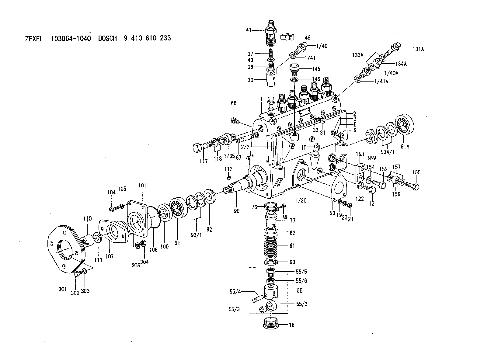
| 1. | [1] | 133050-0820 | PUMP HOUSING |
| 1/30. | [3] | 029040-6020 | STUD |
| 1/35. | [1] | 132400-0900 | ADAPTOR |
| 1/40. | [1] | 131420-0420 | BLEEDER SCREW |
| 1/40A. | [1] | 131423-0200 | ADAPTOR |
| 1/41. | [1] | 026512-1540 | GASKET |
| 1/41A. | [1] | 026512-1540 | GASKET |
| 2. | [1] | 133010-4620 | COVER |
| 2/2. | [1] | 133011-0100 | GASKET |
| 3. | [3] | 133017-0100 | FLAT-HEAD SCREW |
| 5. | [3] | 026508-1240 | GASKET D11.9&8.2T1.0 |
| 9. | [3] | 133023-0100 | CAP NUT |
| 15. | [1] | 133030-1220 | LEVEL INDICATOR |
| 16. | [6] | 133034-0400 | CAPSULE |
| 19. | [3] | 029300-6030 | PLAIN WASHER |
| 20. | [3] | 014110-6410 | LOCKING WASHER |
| 21. | [3] | 013020-6040 | UNION NUT |
| 23. | [1] | 133041-0400 | GASKET |
| 30. | [6] | 133151-1120 | PLUNGER-AND-BARREL ASSY 416NP4 |
| 31. | [6] | 133106-0600 | CAPSULE |
| 32. | [6] | 029330-8110 | GASKET |
| 36. | [6] | 133110-0120 | DELIVERY-VALVE ASSEMBLY 4/2 |
| 37. | [6] | 133112-0100 | COMPRESSION SPRING |
| 40. | [6] | 133115-0600 | GASKET |
| 41. | [6] | 133116-1600 | FITTING |
| 45. | [3] | 133122-1420 | PLATE |
| 55. | [6] | 133200-0120 | TAPPET |
| 55/2. | [6] | 133204-0200 | ROLLER |
| 55/3. | [6] | 133205-0200 | BUSHING |
| 55/4. | [6] | 133203-0200 | BEARING PIN |
| 55/5. | [6] | 133202-0100 | HEXAGON SCREW |
| 55/6. | [6] | 133201-0101 | UNION NUT |
| 61. | [6] | 133215-0100 | COMPRESSION SPRING |
| 62. | [6] | 133216-0100 | SLOTTED WASHER |
| 63. | [6] | 133217-0100 | SLOTTED WASHER |
| 67. | [1] | 133256-0000 | CONTROL RACK |
| 68. | [1] | 132226-0400 | FLAT-HEAD SCREW |
| 76. | [6] | 133240-0100 | PINION |
| 77. | [6] | 133241-0200 | CONTROL SLEEVE |
| 78. | [6] | 131242-0100 | FLAT-HEAD SCREW |
| 90. | [1] | 133370-0001 | CAMSHAFT |
| 91. | [1] | 016650-3030 | BEARING PLATE |
| 91A. | [1] | 016650-3030 | BEARING PLATE |
| 92. | [1] | 133302-0100 | SPACER RING |
| 92A. | [1] | 133302-0100 | SPACER RING |
| 93/1. | [0] | 029312-6010 | SHIM D40&26T0.1 |
| 93/1. | [0] | 029312-6020 | SHIM D40&26T0.12 |
| 93/1. | [0] | 029312-6030 | SHIM D40&26T0.14 |
| 93/1. | [0] | 029312-6040 | SHIM D40&26T0.16 |
| 93/1. | [0] | 029312-6050 | SHIM D40&26T0.18 |
| 93/1. | [0] | 029312-6060 | SHIM D40&26T0.5 |
| 93A/1. | [0] | 029312-6010 | SHIM D40&26T0.1 |
| 93A/1. | [0] | 029312-6020 | SHIM D40&26T0.12 |
| 93A/1. | [0] | 029312-6030 | SHIM D40&26T0.14 |
| 93A/1. | [0] | 029312-6040 | SHIM D40&26T0.16 |
| 93A/1. | [0] | 029312-6050 | SHIM D40&26T0.18 |
| 93A/1. | [0] | 029312-6060 | SHIM D40&26T0.5 |
| 100. | [1] | 029622-5010 | PACKING RING |
| 101. | [1] | 133316-0500 | COVER |
| 104. | [4] | 029010-8020 | BLEEDER SCREW |
| 105. | [4] | 014110-8440 | LOCKING WASHER D15.4&8.2T2 |
| 106. | [1] | 029637-2000 | O-RING |
| 107. | [1] | 156611-0400 | COUPLING PLATE |
| 110. | [1] | 029231-8010 | UNION NUT |
| 111. | [1] | 014111-8410 | LOCKING WASHER |
| 112. | [1] | 025805-1910 | WOODRUFF KEY |
| 117. | [1] | 029731-8210 | EYE BOLT |
| 118. | [2] | 026518-2240 | GASKET |
| 121. | [1] | 029111-0020 | CAPSULE |
| 122. | [1] | 026510-1440 | GASKET |
| 131A. | [1] | 131424-1420 | OVER FLOW VALVE |
| 133A. | [2] | 029331-4230 | GASKET |
| 134A. | [1] | 027114-1040 | INLET UNION |
| 145. | [1] | 155406-0220 | AIR FILTER |
| 146. | [1] | 026512-1640 | GASKET |
| 152. | [1] | 027414-2640 | EYE BOLT |
| 153. | [1] | 133431-0520 | CONNECTOR |
| 154. | [1] | 026514-1840 | GASKET |
| 155. | [1] | 029731-2230 | EYE BOLT |
| 156. | [1] | 027112-0840 | INLET UNION |
| 157. | [2] | 026512-1540 | GASKET |
| 301. | [6] | 156605-0200 | PLATE |
| 302. | [2] | 156603-1300 | BLEEDER SCREW |
| 303. | [2] | 156615-0100 | PLAIN WASHER |
| 304. | [2] | 029201-0140 | UNION NUT |
| 305. | [2] | 014111-0410 | LOCKING WASHER |
Cross reference number
Zexel num
Bosch num
Firm num
Name
103064-1040
FUEL-INJECTION PUMP
Q 14BS FUEL INJECTION PUMP PE4-8Z PE
Q 14BS FUEL INJECTION PUMP PE4-8Z PE
Information:
941B 80H3884-Up
(1) Remove the engine from the machine; see the Service Manual for the procedure. Put both engines, new and old, in a position that will give good access to their front, rear, top and both sides. For those engines that were equipped with glow plugs, either remove the wire from the heat-start switch to the glow plug lead assembly, or put tape over the end of the wire when it is disconnected. This wire will not be needed because the new engine does not have glow plugs.(2) From the old engine, remove the crankshaft pulley and hub, engine front support, the rear supports (from the sides of the flywheel housing) and the flywheel. Install these
(1) Remove the engine from the machine; see the Service Manual for the procedure. Put both engines, new and old, in a position that will give good access to their front, rear, top and both sides. For those engines that were equipped with glow plugs, either remove the wire from the heat-start switch to the glow plug lead assembly, or put tape over the end of the wire when it is disconnected. This wire will not be needed because the new engine does not have glow plugs.(2) From the old engine, remove the crankshaft pulley and hub, engine front support, the rear supports (from the sides of the flywheel housing) and the flywheel. Install these