Information fuel-injection pump
BOSCH
9 411 615 202
9411615202
ZEXEL
102751-0001
1027510001

Rating:
Scheme ###:
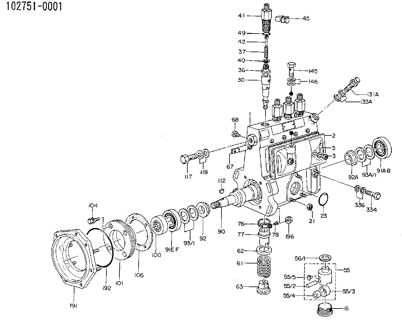
| 1. | [1] | 137500-0020 | PUMP HOUSING |
| 2. | [1] | 131013-5320 | COVER |
| 3. | [2] | 131017-1000 | FLAT-HEAD SCREW |
| 5. | [2] | 029340-6020 | GASKET D10&6.5T1.00 |
| 16. | [4] | 131034-1501 | CAPSULE |
| 21. | [3] | 139206-0400 | UNION NUT |
| 23. | [1] | 029633-1010 | O-RING |
| 30. | [4] | 137500-0320 | PLUNGER-AND-BARREL ASSY |
| 36. | [4] | 137500-0420 | DELIVERY-VALVE ASSEMBLY |
| 37. | [4] | 137500-0500 | COILED SPRING |
| 40. | [4] | 131115-0800 | GASKET |
| 41. | [4] | 137500-0620 | FITTING |
| 42. | [4] | 137500-0800 | FILLER PIECE |
| 45. | [2] | 131122-0520 | PLATE |
| 49. | [4] | 139720-0200 | O-RING |
| 55. | [3] | 131200-2720 | TAPPET |
| 55/2. | [1] | 131203-0500 | BEARING PIN |
| 55/3. | [1] | 131204-1100 | ROLLER |
| 55/4. | [1] | 131205-0600 | BUSHING |
| 55/5. | [1] | 131206-0700 | SLIDER |
| 55A. | [1] | 137500-0920 | TAPPET |
| 55A/2. | [1] | 131203-0500 | BEARING PIN |
| 55A/3. | [1] | 131204-1100 | ROLLER |
| 55A/4. | [1] | 131205-0600 | BUSHING |
| 55A/5. | [1] | 131206-0700 | SLIDER |
| 56/1. | [0] | 029311-0020 | SHIM D19&10T0.30 |
| 56/1. | [0] | 029311-0030 | SHIM D19&10T0.40 |
| 56/1. | [0] | 029311-0040 | SHIM D19&10T0.50 |
| 56/1. | [0] | 029311-0050 | SHIM D19&10T0.6 |
| 56/1. | [0] | 029311-0060 | SHIM D19&10T0.7 |
| 56/1. | [0] | 029311-0070 | SHIM D19&10T0.8 |
| 56/1. | [0] | 029311-0080 | SHIM D19&10T0.9 |
| 56/1. | [0] | 029311-0090 | SHIM D19&10T1 |
| 56/1. | [0] | 029311-0110 | SHIM D19&10T1.1 |
| 56/1. | [0] | 029311-0120 | SHIM D19&10T1.2 |
| 56/1. | [0] | 029311-0130 | SHIM D19&10T1.3 |
| 56/1. | [0] | 029311-0140 | SHIM D19&10T1.4 |
| 56/1. | [0] | 029311-0270 | SHIM D19&10T0.55 |
| 56/1. | [0] | 029311-0280 | SHIM D19&10T0.65 |
| 56/1. | [0] | 029311-0290 | SHIM D19&10T0.75 |
| 56/1. | [0] | 029311-0310 | SHIM D19&10T0.85 |
| 56/1. | [0] | 029311-0320 | SHIM D19&10T0.95 |
| 56/1. | [0] | 029311-0330 | SHIM D19&10T1.05 |
| 56/1. | [0] | 029311-0340 | SHIM D19&10T1.15 |
| 56/1. | [0] | 029311-0350 | SHIM D19&10T1.25 |
| 56/1. | [0] | 029311-0490 | SHIM D19&10T1.5 |
| 56/1. | [0] | 029311-0500 | SHIM D19&10T1.6 |
| 56/1. | [0] | 029311-0580 | SHIM D19&10T0.2 |
| 56/1. | [0] | 029311-0590 | SHIM D19&10T0.25 |
| 56/1. | [0] | 029311-0600 | SHIM D19&10T0.35 |
| 56/1. | [0] | 029311-0610 | SHIM D19&10T0.45 |
| 56/1. | [0] | 029311-0620 | SHIM D19&10T1.35 |
| 56/1. | [0] | 029311-0630 | SHIM D19&10T1.45 |
| 56/1. | [0] | 029311-0710 | SHIM D19&10T1.55 |
| 61. | [4] | 131215-1600 | COMPRESSION SPRING |
| 62. | [4] | 131216-0400 | SLOTTED WASHER |
| 63. | [4] | 131217-0600 | SLOTTED WASHER |
| 67. | [1] | 131254-0000 | CONTROL RACK |
| 68. | [1] | 131226-0300 | FLAT-HEAD SCREW |
| 76. | [4] | 131240-0100 | PINION |
| 77. | [4] | 131241-0500 | CONTROL SLEEVE |
| 78. | [4] | 131242-0100 | FLAT-HEAD SCREW |
| 90. | [1] | 131365-0700 | CAMSHAFT |
| 91A. | [1] | 016630-2030 | BEARING PLATE |
| 91B. | [1] | 028201-7020 | BEARING PLATE |
| 91E. | [1] | 016640-2030 | BEARING PLATE |
| 91F. | [1] | 028202-0020 | BEARING PLATE |
| 92. | [1] | 131302-1000 | SPACER RING |
| 92A. | [1] | 131302-0400 | SPACER RING |
| 93/1. | [0] | 029312-0220 | SHIM D27&20T0.1 |
| 93/1. | [0] | 029312-0230 | SHIM D27&20T0.12 |
| 93/1. | [0] | 029312-0240 | SHIM D27&20T0.14 |
| 93/1. | [0] | 029312-0250 | SHIM D27&20T0.16 |
| 93/1. | [0] | 029312-0260 | SHIM D27&20T0.18 |
| 93/1. | [0] | 029312-0270 | SHIM D27&20T0.5 |
| 93/1. | [0] | 029312-0290 | SHIM D27&20T0.3 |
| 93/1. | [0] | 029312-0300 | SHIM D27&20T1.0 |
| 93/1. | [0] | 139420-0400 | SHIM D27&20T0.7 |
| 93A/1. | [0] | 029311-7010 | SHIM D22&17T0.1 |
| 93A/1. | [0] | 029311-7020 | SHIM D22&17T0.12 |
| 93A/1. | [0] | 029311-7030 | SHIM D22&17T0.14 |
| 93A/1. | [0] | 029311-7040 | SHIM D22&17T0.16 |
| 93A/1. | [0] | 029311-7050 | SHIM D22&17T0.18 |
| 93A/1. | [0] | 029311-7060 | SHIM D22&17T0.5 |
| 93A/1. | [0] | 029311-7070 | SHIM D22&17T1.0 |
| 93A/1. | [0] | 029311-7090 | SHIM D22&17T0.3 |
| 93A/1. | [0] | 029311-7210 | SHIM D22&17T0.7 |
| 93A/1. | [0] | 029311-7220 | SHIM D22&17T1.4 |
| 93A/1. | [0] | 139417-0000 | SHIM D22&17T2.4 |
| 100. | [1] | 029622-0190 | PACKING RING |
| 101. | [1] | 131330-1300 | COVER |
| 104. | [4] | 020006-2040 | BLEEDER SCREW M6P1L20 4T |
| 106. | [1] | 131321-1900 | GASKET |
| 112. | [1] | 029470-4030 | WOODRUFF KEY |
| 117. | [1] | 137500-1000 | EYE BOLT |
| 118. | [2] | 029341-4130 | GASKET D20&13.8T2* |
| 131A. | [1] | 137500-1120 | OVER FLOW VALVE |
| 133A. | [2] | 029341-4130 | GASKET D20&13.8T2* |
| 145. | [1] | 029731-2040 | EYE BOLT |
| 146. | [2] | 026512-1540 | GASKET D15.4&12.2T1.50 |
| 191. | [1] | 137500-1420 | BRACKET |
| 192. | [1] | 029637-5020 | O-RING &73.5W2 |
| 196. | [4] | 137500-1500 | UNION NUT |
| 334. | [1] | 029731-0120 | EYE BOLT |
| 336. | [2] | 029341-0110 | GASKET |
Cross reference number
Zexel num
Bosch num
Firm num
Name
Information:
Start By:a. remove flywheelb. remove crankshaft rear seal and wear sleeve **Remove the crankshaft rear seal and wear sleeve only if the engine is equipped with the later design seal. The later design seal can be identified by the rotation marks on the seal.
Some flywheel housings will have more bolts holding the flywheel housing to the cylinder block.
1. If the engine is equipped with an electric starting motor, remove the electric starting motor from the flywheel housing.2. Remove the bolts that hold the oil pan plate to the flywheel housing. Loosen the bolts that hold the oil pan plate to the cylinder block.3. Install spacers between the oil pan plate and the cylinder block to hold the oil pan plate away from the flywheel housing.
3306 Engine Shown4. On 3306 Engines, remove turbocharger oil drain pipe (1).5. Install Tool (A) on the flywheel housing as shown, and fasten a hoist to it.6. Remove all bolts (2) and the flywheel housing from the engine. The weight of the flywheel housing is 37 kg (82 lb).Install Flywheel Housing
3306 Engine Shown1. Install Tool (A) on the flywheel housing. Fasten a hoist to the flywheel housing. 2. Put the gasket and flywheel housing in position on the engine. Install bolts (2) that hold it. Tighten the bolts to a torque of 100 14 N m (74 10 lb ft) as shown.3. Remove Tool (A) from the flywheel housing.4. On 3306 Engines, install turbocharger oil drain line (1).5. Cut the bottom of the flywheel housing gasket off even with the cylinder block and flywheel housing. Put 3S6252 RTV Silicone Adhesive/Sealant on the bottom of the gasket where it makes contact with the oil pan plate gasket.6. Remove the spacers from between the oil pan plate and the cylinder block. Install the bolts that hold the oil pan plate to the flywheel housing. Tighten the bolts that hold the oil pan plate to the cylinder block.7. If the engine is equipped with an electric starting motor, install it on the flywheel housing.End By:a. install crankshaft rear seal and wear sleeveb. install flywheel