Information fuel-injection pump
BOSCH
9 410 612 307
9410612307
ZEXEL
101069-3341
1010693341
NISSAN-DIESEL
1670195019
1670195019

Rating:
Scheme ###:
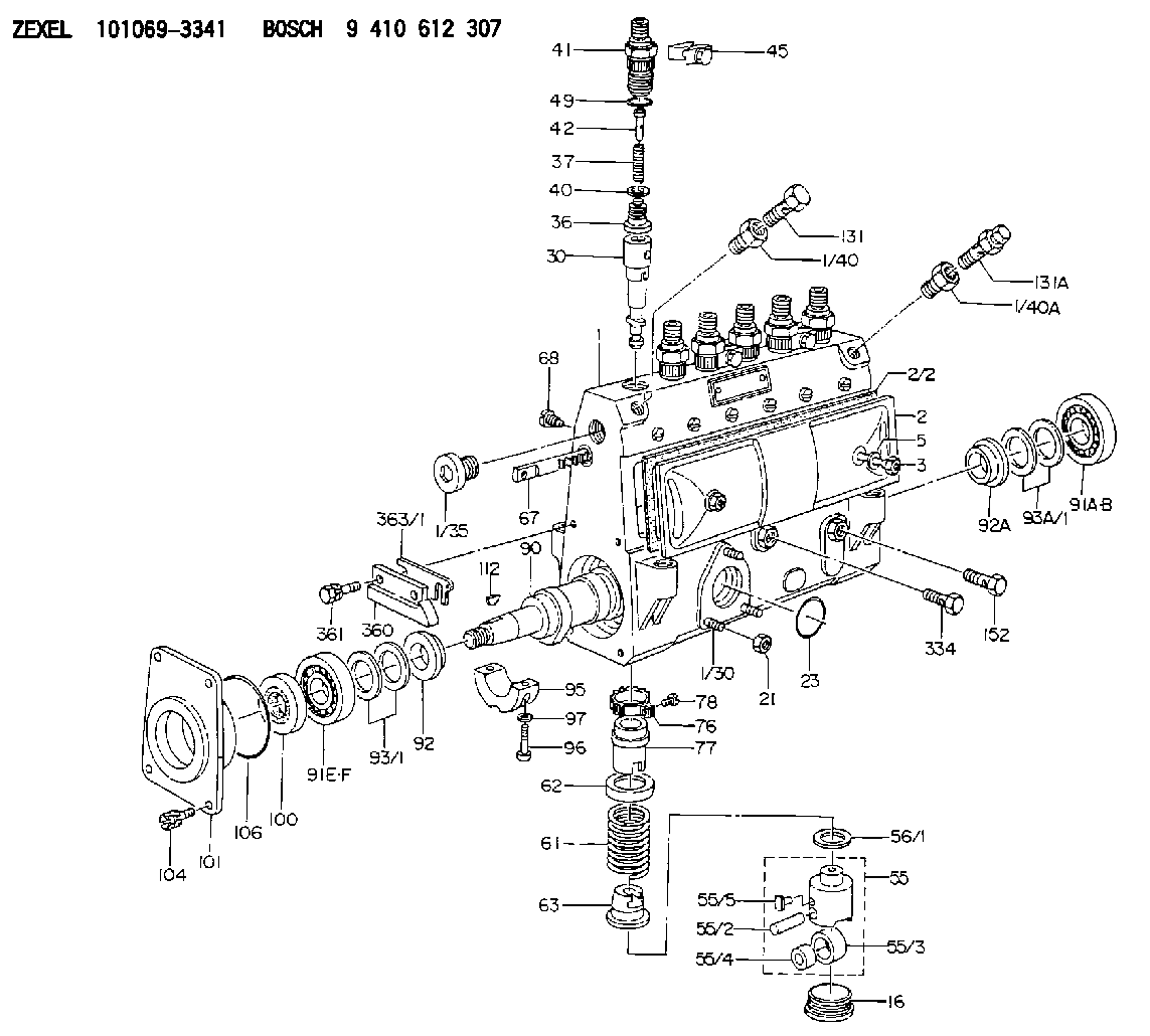
| 1. | [1] | 131071-8320 | PUMP HOUSING |
| 1/30. | [3] | 029040-6020 | STUD |
| 1/35. | [1] | 134026-0000 | CAPSULE |
| 1/40. | [1] | 131002-5500 | ADAPTOR |
| 1/40A. | [1] | 131002-5500 | ADAPTOR |
| 2. | [1] | 131028-6020 | COVER |
| 2/2. | [1] | 131011-0800 | GASKET |
| 3. | [2] | 131017-1000 | FLAT-HEAD SCREW |
| 5. | [2] | 026506-1040 | GASKET D9.9&6.2T1 |
| 16. | [6] | 131034-1401 | CAPSULE |
| 21. | [3] | 139206-0400 | UNION NUT |
| 23. | [1] | 029633-1010 | O-RING |
| 30. | [6] | 131152-5920 | PLUNGER-AND-BARREL ASSY |
| 36. | [6] | 131160-3020 | DELIVERY-VALVE ASSEMBLY |
| 37. | [6] | 131112-4300 | COMPRESSION SPRING |
| 40. | [6] | 131115-1600 | GASKET |
| 41. | [6] | 131116-7600 | FITTING |
| 42. | [6] | 131117-2300 | FILLER PIECE |
| 45. | [3] | 131122-0520 | PLATE |
| 49. | [6] | 029632-0030 | O-RING |
| 55. | [6] | 131200-2820 | TAPPET |
| 55/2. | [1] | 131203-0800 | BEARING PIN |
| 55/3. | [1] | 131204-1000 | ROLLER |
| 55/4. | [1] | 131205-0500 | BUSHING |
| 55/5. | [1] | 131206-0200 | SLIDER |
| 56/1. | [0] | 029311-0020 | SHIM D19&10T0.30 |
| 56/1. | [0] | 029311-0030 | SHIM D19&10T0.40 |
| 56/1. | [0] | 029311-0040 | SHIM D19&10T0.50 |
| 56/1. | [0] | 029311-0050 | SHIM D19&10T0.6 |
| 56/1. | [0] | 029311-0060 | SHIM D19&10T0.7 |
| 56/1. | [0] | 029311-0070 | SHIM D19&10T0.8 |
| 56/1. | [0] | 029311-0080 | SHIM D19&10T0.9 |
| 56/1. | [0] | 029311-0090 | SHIM D19&10T1 |
| 56/1. | [0] | 029311-0110 | SHIM D19&10T1.1 |
| 56/1. | [0] | 029311-0120 | SHIM D19&10T1.2 |
| 56/1. | [0] | 029311-0130 | SHIM D19&10T1.3 |
| 56/1. | [0] | 029311-0140 | SHIM D19&10T1.4 |
| 56/1. | [0] | 029311-0270 | SHIM D19&10T0.55 |
| 56/1. | [0] | 029311-0280 | SHIM D19&10T0.65 |
| 56/1. | [0] | 029311-0290 | SHIM D19&10T0.75 |
| 56/1. | [0] | 029311-0310 | SHIM D19&10T0.85 |
| 56/1. | [0] | 029311-0320 | SHIM D19&10T0.95 |
| 56/1. | [0] | 029311-0330 | SHIM D19&10T1.05 |
| 56/1. | [0] | 029311-0340 | SHIM D19&10T1.15 |
| 56/1. | [0] | 029311-0350 | SHIM D19&10T1.25 |
| 56/1. | [0] | 029311-0490 | SHIM D19&10T1.5 |
| 56/1. | [0] | 029311-0500 | SHIM D19&10T1.6 |
| 56/1. | [0] | 029311-0580 | SHIM D19&10T0.2 |
| 56/1. | [0] | 029311-0590 | SHIM D19&10T0.25 |
| 56/1. | [0] | 029311-0600 | SHIM D19&10T0.35 |
| 56/1. | [0] | 029311-0610 | SHIM D19&10T0.45 |
| 56/1. | [0] | 029311-0620 | SHIM D19&10T1.35 |
| 56/1. | [0] | 029311-0630 | SHIM D19&10T1.45 |
| 56/1. | [0] | 029311-0710 | SHIM D19&10T1.55 |
| 61. | [6] | 131215-2300 | COMPRESSION SPRING |
| 62. | [6] | 131216-0100 | SLOTTED WASHER |
| 63. | [6] | 131217-0200 | SLOTTED WASHER |
| 67. | [1] | 131256-0000 | CONTROL RACK |
| 68. | [1] | 131226-0300 | FLAT-HEAD SCREW |
| 76. | [6] | 131240-0100 | PINION |
| 77. | [6] | 131241-0100 | CONTROL SLEEVE |
| 78. | [6] | 131242-0100 | FLAT-HEAD SCREW |
| 90. | [1] | 131371-3100 | CAMSHAFT |
| 91A. | [1] | 016630-2030 | BEARING PLATE |
| 91B. | [1] | 028201-7020 | BEARING PLATE |
| 91E. | [1] | 016640-2030 | BEARING PLATE |
| 91F. | [1] | 028202-0020 | BEARING PLATE |
| 92. | [1] | 131302-1300 | SPACER RING |
| 92A. | [1] | 131302-0300 | SPACER RING |
| 93/1. | [0] | 029312-0310 | SHIM D24&20T0.10 |
| 93/1. | [0] | 029312-0320 | SHIM D24&20T0.12 |
| 93/1. | [0] | 029312-0330 | SHIM D24&20T0.14 |
| 93/1. | [0] | 029312-0340 | SHIM D24&20T0.16 |
| 93/1. | [0] | 029312-0350 | SHIM D24&20T0.18 |
| 93/1. | [0] | 029312-0360 | SHIM D24&20T0.3 |
| 93/1. | [0] | 029312-0370 | SHIM D24&20T0.5 |
| 93/1. | [0] | 029312-0380 | SHIM D24&20T1.0 |
| 93A/1. | [0] | 029311-7010 | SHIM D22&17T0.1 |
| 93A/1. | [0] | 029311-7020 | SHIM D22&17T0.12 |
| 93A/1. | [0] | 029311-7030 | SHIM D22&17T0.14 |
| 93A/1. | [0] | 029311-7040 | SHIM D22&17T0.16 |
| 93A/1. | [0] | 029311-7050 | SHIM D22&17T0.18 |
| 93A/1. | [0] | 029311-7060 | SHIM D22&17T0.5 |
| 93A/1. | [0] | 029311-7070 | SHIM D22&17T1.0 |
| 93A/1. | [0] | 029311-7090 | SHIM D22&17T0.3 |
| 93A/1. | [0] | 029311-7210 | SHIM D22&17T0.7 |
| 93A/1. | [0] | 029311-7220 | SHIM D22&17T1.4 |
| 93A/1. | [0] | 139417-0000 | SHIM D22&17T2.4 |
| 95. | [1] | 131306-1000 | BEARING SHELL |
| 96. | [2] | 029050-5010 | FLAT-HEAD SCREW M5P0.8L32 |
| 97. | [2] | 026505-0940 | GASKET |
| 100. | [1] | 029622-0240 | PACKING RING |
| 101. | [1] | 131316-2000 | COVER |
| 104. | [4] | 020006-1440 | BLEEDER SCREW M6P1L14 |
| 106. | [1] | 029635-0050 | O-RING |
| 112. | [1] | 025804-1610 | WOODRUFF KEY |
| 131. | [1] | 029731-4680 | EYE BOLT |
| 131A. | [1] | 131424-1520 | OVER FLOW VALVE |
| 152. | [1] | 029731-4680 | EYE BOLT |
| 334. | [1] | 029730-8290 | EYE BOLT |
| 360. | [1] | 131496-0700 | POINTER |
| 361. | [2] | 029010-6700 | BLEEDER SCREW |
| 363/1. | [0] | 139400-0500 | SHIM T0.20 |
| 363/1. | [0] | 139400-0600 | SHIM T0.30 |
| 363/1. | [0] | 139400-0700 | SHIM T0.50 |
| 363/1. | [0] | 139400-0800 | SHIM T1.00 |
Cross reference number
Zexel num
Bosch num
Firm num
Name
Information:
Communicating with the Wireless Communication Adapter
Table 23 lists the optional hardware that is needed in order to connect Cat ET by using a wireless connection.
Table 23
Optional Hardware for the Use of Cat ET
Part Number Description
N/A Personal Computer (PC)
261-3363 (1) Wireless Communication Adapter Gp
( 1 ) Refer to Tool Operating Manual, "Using the 261-3363 Wireless Communication Adapter Gp " for information that is related to the installation and the configuration.
Illustration 81 g01297379
(1) Personal computer (PC) (7) 261-4867 Card (PCMCIA) (8) 239-9955 Communication Radio Gp (9) 259-3183 Data Link Cable As Note: Items (7), (8), and (9) are part of the 261-3363 Wireless Communication Adapter Gp .Use the following procedure in order to connect the wireless communication adapter for use with Cat ET.
Remove the electrical power from the ECM.
Ensure that the computer has been correctly configured for the 261-4867 Card (PCMCIA). Verify that the PC card is installed in the computer PCI expansion slot.
Connect cable (9) between communication radio (8) and the service tool connector.
Restore the electrical power to the ECM. If Cat ET and the communication radio do not communicate with the ECM, refer to troubleshooting without a diagnostic code Troubleshooting, "Electronic Service Tool Will Not Communicate with ECM".Starting System
The EUI system requires that the crankshaft rotate at a minimum of 70 rpm. The engine starting system must be able to supply the air pressure and flow to the starting motor in order to start the engine. The vane type starting motors may be replaced with turbine type starting motors.If the existing starting system does not meet the 70 rpm requirement, the starting motors must be replaced with turbine type starting motors. Refer to Table 24 for a list of part numbers for the recommended turbine type starting motors for 3600 Engines. For a dual starting motor application, two of the motor group part number must be ordered.Air lines to the starting motors must be modified for the turbine starters. A lubricating device is not required for the turbine type starting motors. Any lubricating device must be removed. The air lines for a single starting motor must have a minimum diameter of 38.1 mm (1.5 inch). Air lines for dual starting motors must have a minimum diameter of 76.2 mm (3.0 inch).
Table 24
Turbine Type Starting Motors for 3600 Engine Applications
Sales Model Standard Rotation Reverse Rotation Quantity
3606 and 3608 269-3839 275-8518 1
3612 (1) 295-6006 295-6007
246-1241 246-4483 2
3616
( 1 ) 3612 Engines can be started by dual starting motors or by a single starting motor. A single starting motor may only be used in cases when minimal parasitic torque is coupled to the engine during cranking. Dual starters may be required in applications when a 3612 Engine must be started in cold ambient conditions. Cold ambient condition will raise the viscosity of the