Information fuel-injection pump
BOSCH
9 410 612 919
9410612919
ZEXEL
101067-1650
1010671650
NISSAN-DIESEL
16703Z5002
16703z5002

Rating:
Scheme ###:
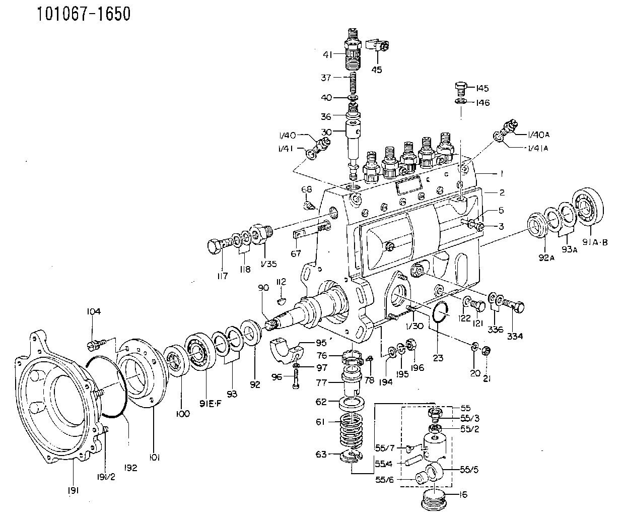
| 1. | [1] | 131073-5820 | PUMP HOUSING |
| 1/30. | [3] | 029040-6020 | STUD |
| 1/35. | [1] | 131400-0100 | ADAPTOR |
| 1/40. | [1] | 131420-0420 | BLEEDER SCREW |
| 1/40A. | [1] | 131420-0420 | BLEEDER SCREW |
| 1/41. | [1] | 026512-1540 | GASKET D15.4&12.2T1.50 |
| 1/41A. | [1] | 026512-1540 | GASKET D15.4&12.2T1.50 |
| 2. | [1] | 131028-6020 | COVER |
| 2/2. | [1] | 131011-0800 | GASKET |
| 3. | [2] | 131017-1000 | FLAT-HEAD SCREW |
| 5. | [2] | 029340-6020 | GASKET D10&6.5T1.00 |
| 16. | [6] | 131034-1401 | CAPSULE |
| 21. | [3] | 139206-0400 | UNION NUT |
| 23. | [1] | 029633-1010 | O-RING |
| 30. | [6] | 131151-5420 | PLUNGER-AND-BARREL ASSY |
| 36. | [6] | 131110-0520 | DELIVERY-VALVE ASSEMBLY |
| 37. | [6] | 131112-0300 | COILED SPRING |
| 40. | [6] | 131115-0200 | GASKET |
| 41. | [6] | 131116-0820 | FITTING |
| 45. | [3] | 131122-0520 | PLATE |
| 55. | [6] | 131200-0620 | TAPPET |
| 55/2. | [1] | 131201-0100 | UNION NUT |
| 55/3. | [1] | 131202-0100 | HEXAGON SCREW |
| 55/4. | [1] | 131203-0200 | BEARING PIN |
| 55/5. | [1] | 131204-1000 | ROLLER |
| 55/6. | [1] | 131205-0500 | BUSHING |
| 55/7. | [1] | 131206-0200 | SLIDER |
| 61. | [6] | 131215-2400 | COMPRESSION SPRING |
| 62. | [6] | 131216-0100 | SLOTTED WASHER |
| 63. | [6] | 131217-0100 | SLOTTED WASHER |
| 67. | [1] | 131256-0000 | CONTROL RACK |
| 68. | [1] | 131226-0300 | FLAT-HEAD SCREW |
| 76. | [6] | 131240-0100 | PINION |
| 77. | [6] | 131241-0100 | CONTROL SLEEVE |
| 78. | [6] | 131242-0100 | FLAT-HEAD SCREW |
| 90. | [1] | 131370-0900 | CAMSHAFT |
| 91A. | [1] | 016630-2030 | BEARING PLATE |
| 91B. | [1] | 028201-7020 | BEARING PLATE |
| 91E. | [1] | 016630-2030 | BEARING PLATE |
| 91F. | [1] | 028201-7020 | BEARING PLATE |
| 92. | [1] | 131302-0300 | SPACER RING |
| 92A. | [1] | 131302-0300 | SPACER RING |
| 93/1. | [0] | 029311-7010 | SHIM D22&17T0.1 |
| 93/1. | [0] | 029311-7020 | SHIM D22&17T0.12 |
| 93/1. | [0] | 029311-7030 | SHIM D22&17T0.14 |
| 93/1. | [0] | 029311-7040 | SHIM D22&17T0.16 |
| 93/1. | [0] | 029311-7050 | SHIM D22&17T0.18 |
| 93/1. | [0] | 029311-7060 | SHIM D22&17T0.5 |
| 93/1. | [0] | 029311-7070 | SHIM D22&17T1.0 |
| 93/1. | [0] | 029311-7090 | SHIM D22&17T0.3 |
| 93/1. | [0] | 029311-7210 | SHIM D22&17T0.7 |
| 93/1. | [0] | 029311-7220 | SHIM D22&17T1.4 |
| 93/1. | [0] | 139417-0000 | SHIM D22&17T2.4 |
| 93A/1. | [0] | 029311-7010 | SHIM D22&17T0.1 |
| 93A/1. | [0] | 029311-7020 | SHIM D22&17T0.12 |
| 93A/1. | [0] | 029311-7030 | SHIM D22&17T0.14 |
| 93A/1. | [0] | 029311-7040 | SHIM D22&17T0.16 |
| 93A/1. | [0] | 029311-7050 | SHIM D22&17T0.18 |
| 93A/1. | [0] | 029311-7060 | SHIM D22&17T0.5 |
| 93A/1. | [0] | 029311-7070 | SHIM D22&17T1.0 |
| 93A/1. | [0] | 029311-7090 | SHIM D22&17T0.3 |
| 93A/1. | [0] | 029311-7210 | SHIM D22&17T0.7 |
| 93A/1. | [0] | 029311-7220 | SHIM D22&17T1.4 |
| 93A/1. | [0] | 139417-0000 | SHIM D22&17T2.4 |
| 95. | [1] | 131306-0800 | BEARING SHELL |
| 96. | [2] | 029050-5010 | FLAT-HEAD SCREW M5P0.8L32 |
| 97. | [2] | 026505-0940 | GASKET |
| 100. | [1] | 029621-7050 | PACKING RING |
| 101. | [1] | 131330-2200 | COVER |
| 104. | [4] | 020006-1440 | BLEEDER SCREW M6P1L14 |
| 112. | [1] | 025803-1610 | WOODRUFF KEY |
| 117. | [1] | 029731-4080 | EYE BOLT |
| 121. | [1] | 029111-0010 | CAPSULE |
| 122. | [1] | 029341-0020 | GASKET |
| 191. | [1] | 131459-4120 | BRACKET |
| 191/2. | [4] | 029041-0010 | STUD |
| 192. | [1] | 139768-0000 | O-RING |
| 194. | [4] | 014011-0140 | PLAIN WASHER D22&10.5T1.6 |
| 195. | [4] | 014111-0440 | LOCKING WASHER |
| 196. | [4] | 131465-0000 | UNION NUT |
| 334. | [1] | 029731-0120 | EYE BOLT |
| 336. | [2] | 026510-1340 | GASKET D13.4&10.2T1 |
Cross reference number
Zexel num
Bosch num
Firm num
Name
101067-1650
9 410 612 919
16703Z5002 NISSAN-DIESEL
FUEL-INJECTION PUMP
* Q
* Q
Information:
Monitor
Illustration 1 g00856663
(1) Display (2) Indicators (3) Bezel With Stud Mounting (Standard NEMA Type 4)Connectors
Illustration 2 g00856664
(4) I/O Card (5) CPU Card (6) Shared PCI/ISA Expansion Slot (7) Serial Port 1 (DB9) (8) Backlight Dimming Control (9) PCI Slot (10) Video Port (HD-15) (11) Ethernet Connection (RJ45) (12) Parallel Port (DB25) (13) 2 USB Ports (14) 3.5" Internal Hard Drive (15) PS/2 Keyboard Connector (Mini DIN) (16) 3.5" Floppy Drive (17) PS/2 Mouse Connector (Mini DIN) (18) Cooling Fan and Filter (Bottom)Indicators
The following tables describe the indicators on the monitor. The labels for the indicators are symbols.
Illustration 3 g00856666
Diagnostic Indicator
Table 1
Position Color Description
Left Red Diagnostics The diagnostic indicator shows when one of the following conditions exists:Over Temperature - The temperature inside of the monitor enclosure is above the defined threshold.Fan Sensor - The system fan is not operating within the defined thresholds.Voltage - The voltages are not within the specifications.Refer to Troubleshooting, "Diagnostic Indicator Is On - Troubleshoot" for information on resolving diagnostic conditions.
Illustration 4 g00856667
Hard Drive Access Indicator
Table 2
Position Color Description
Center Green Hard Drive Access
Illustration 5 g00856668
Power On Indicator
Table 3
Position Color Description
Right Green Power On Backlight Dimming Control
Use the backlight dimming control (8) in order to vary the screen lighting for optimum viewing.Turn the control clockwise in order to increase the brightness of the display. Turn the control counterclockwise in order to dim the display backlight.
Have questions with 101067-1650?
Group cross 101067-1650 ZEXEL
Nissan-Diesel
101067-1650
9 410 612 919
16703Z5002
FUEL-INJECTION PUMP