Information fuel-injection pump
BOSCH
9 410 612 773
9410612773
ZEXEL
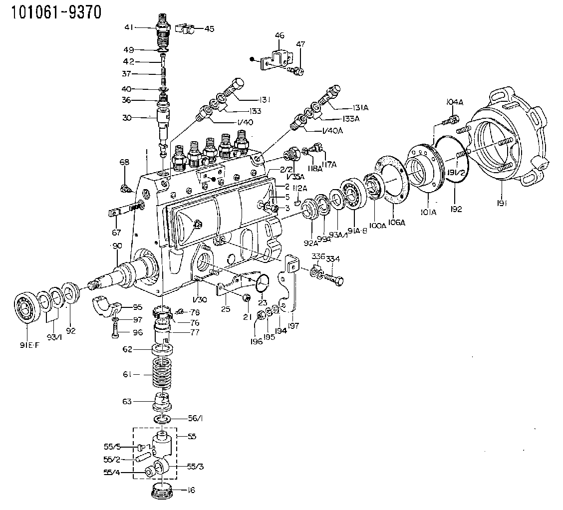
101061-9370
1010619370
MITSUBISHI
ME727278
me727278
Rating:
Scheme ###:
| 1. | [1] | 131074-0620 | PUMP HOUSING |
| 1/30. | [3] | 029040-6220 | STUD |
| 1/35A. | [1] | 134419-0000 | ADAPTOR |
| 1/40. | [1] | 131002-2000 | ADAPTOR |
| 1/40A. | [1] | 131423-1300 | ADAPTOR |
| 2. | [1] | 131028-6620 | COVER |
| 2/2. | [1] | 131011-0800 | GASKET |
| 3. | [2] | 131017-1000 | FLAT-HEAD SCREW |
| 5. | [2] | 029340-6020 | GASKET D10&6.5T1.00 |
| 16. | [6] | 131034-1401 | CAPSULE |
| 21. | [3] | 139206-0400 | UNION NUT |
| 23. | [1] | 029633-1010 | O-RING |
| 25. | [1] | 131563-1500 | BRACKET |
| 30. | [6] | 131152-5220 | PLUNGER-AND-BARREL ASSY |
| 36. | [6] | 131160-4520 | DELIVERY-VALVE ASSEMBLY |
| 37. | [6] | 131112-3500 | COMPRESSION SPRING |
| 40. | [6] | 131115-1600 | GASKET |
| 41. | [6] | 131116-7600 | FITTING |
| 42. | [6] | 131117-2300 | FILLER PIECE |
| 45. | [3] | 131122-0320 | PLATE |
| 46. | [1] | 131563-3300 | BRACKET |
| 47. | [2] | 020106-1040 | BLEEDER SCREW M6P1L12 |
| 49. | [6] | 029632-0030 | O-RING |
| 55. | [6] | 131200-2820 | TAPPET |
| 55/2. | [1] | 131203-0800 | BEARING PIN |
| 55/3. | [1] | 131204-1000 | ROLLER |
| 55/4. | [1] | 131205-0500 | BUSHING |
| 55/5. | [1] | 131206-0200 | SLIDER |
| 56/1. | [0] | 029311-0020 | SHIM D19&10T0.30 |
| 56/1. | [0] | 029311-0030 | SHIM D19&10T0.40 |
| 56/1. | [0] | 029311-0040 | SHIM D19&10T0.50 |
| 56/1. | [0] | 029311-0050 | SHIM D19&10T0.6 |
| 56/1. | [0] | 029311-0060 | SHIM D19&10T0.7 |
| 56/1. | [0] | 029311-0070 | SHIM D19&10T0.8 |
| 56/1. | [0] | 029311-0080 | SHIM D19&10T0.9 |
| 56/1. | [0] | 029311-0090 | SHIM D19&10T1 |
| 56/1. | [0] | 029311-0110 | SHIM D19&10T1.1 |
| 56/1. | [0] | 029311-0120 | SHIM D19&10T1.2 |
| 56/1. | [0] | 029311-0130 | SHIM D19&10T1.3 |
| 56/1. | [0] | 029311-0140 | SHIM D19&10T1.4 |
| 56/1. | [0] | 029311-0270 | SHIM D19&10T0.55 |
| 56/1. | [0] | 029311-0280 | SHIM D19&10T0.65 |
| 56/1. | [0] | 029311-0290 | SHIM D19&10T0.75 |
| 56/1. | [0] | 029311-0310 | SHIM D19&10T0.85 |
| 56/1. | [0] | 029311-0320 | SHIM D19&10T0.95 |
| 56/1. | [0] | 029311-0330 | SHIM D19&10T1.05 |
| 56/1. | [0] | 029311-0340 | SHIM D19&10T1.15 |
| 56/1. | [0] | 029311-0350 | SHIM D19&10T1.25 |
| 56/1. | [0] | 029311-0490 | SHIM D19&10T1.5 |
| 56/1. | [0] | 029311-0500 | SHIM D19&10T1.6 |
| 56/1. | [0] | 029311-0580 | SHIM D19&10T0.2 |
| 56/1. | [0] | 029311-0590 | SHIM D19&10T0.25 |
| 56/1. | [0] | 029311-0600 | SHIM D19&10T0.35 |
| 56/1. | [0] | 029311-0610 | SHIM D19&10T0.45 |
| 56/1. | [0] | 029311-0620 | SHIM D19&10T1.35 |
| 56/1. | [0] | 029311-0630 | SHIM D19&10T1.45 |
| 56/1. | [0] | 029311-0710 | SHIM D19&10T1.55 |
| 61. | [6] | 131215-2300 | COMPRESSION SPRING |
| 62. | [6] | 131216-0100 | SLOTTED WASHER |
| 63. | [6] | 131217-0200 | SLOTTED WASHER |
| 67. | [1] | 131256-0000 | CONTROL RACK |
| 68. | [1] | 131226-0300 | FLAT-HEAD SCREW |
| 76. | [6] | 131240-0100 | PINION |
| 77. | [6] | 131241-0100 | CONTROL SLEEVE |
| 78. | [6] | 131242-0100 | FLAT-HEAD SCREW |
| 90. | [1] | 131371-2500 | CAMSHAFT |
| 91A. | [1] | 016640-2030 | BEARING PLATE |
| 91B. | [1] | 028202-0020 | BEARING PLATE |
| 91E. | [1] | 016630-2030 | BEARING PLATE |
| 91F. | [1] | 028201-7020 | BEARING PLATE |
| 92. | [1] | 131302-0400 | SPACER RING |
| 92A. | [1] | 131302-1300 | SPACER RING |
| 93/1. | [0] | 029311-7010 | SHIM D22&17T0.1 |
| 93/1. | [0] | 029311-7020 | SHIM D22&17T0.12 |
| 93/1. | [0] | 029311-7030 | SHIM D22&17T0.14 |
| 93/1. | [0] | 029311-7040 | SHIM D22&17T0.16 |
| 93/1. | [0] | 029311-7050 | SHIM D22&17T0.18 |
| 93/1. | [0] | 029311-7060 | SHIM D22&17T0.5 |
| 93/1. | [0] | 029311-7070 | SHIM D22&17T1.0 |
| 93/1. | [0] | 029311-7090 | SHIM D22&17T0.3 |
| 93/1. | [0] | 029311-7210 | SHIM D22&17T0.7 |
| 93/1. | [0] | 029311-7220 | SHIM D22&17T1.4 |
| 93/1. | [0] | 139417-0000 | SHIM D22&17T2.4 |
| 93A/1. | [0] | 029312-0310 | SHIM D24&20T0.10 |
| 93A/1. | [0] | 029312-0320 | SHIM D24&20T0.12 |
| 93A/1. | [0] | 029312-0330 | SHIM D24&20T0.14 |
| 93A/1. | [0] | 029312-0340 | SHIM D24&20T0.16 |
| 93A/1. | [0] | 029312-0350 | SHIM D24&20T0.18 |
| 93A/1. | [0] | 029312-0360 | SHIM D24&20T0.3 |
| 93A/1. | [0] | 029312-0370 | SHIM D24&20T0.5 |
| 93A/1. | [0] | 029312-0380 | SHIM D24&20T1.0 |
| 95. | [1] | 131306-1000 | BEARING SHELL |
| 96. | [2] | 029050-5010 | FLAT-HEAD SCREW M5P0.8L32 |
| 97. | [2] | 026505-0940 | GASKET |
| 99A. | [1] | 131330-4000 | PLATE |
| 100A. | [1] | 029622-0190 | PACKING RING |
| 101A. | [1] | 131330-1800 | COVER |
| 104A. | [4] | 020006-2040 | BLEEDER SCREW M6P1L20 4T |
| 106A. | [1] | 131321-1900 | GASKET |
| 112A. | [1] | 029470-4030 | WOODRUFF KEY |
| 117A. | [1] | 131420-0400 | BLEEDER SCREW |
| 118A. | [1] | 026506-1040 | GASKET D9.9&6.2T1 |
| 131. | [1] | 139814-0900 | EYE BOLT |
| 131A. | [1] | 131424-5520 | OVER FLOW VALVE |
| 133. | [2] | 029341-4130 | GASKET D20&13.8T2* |
| 133A. | [2] | 029341-4130 | GASKET D20&13.8T2* |
| 191. | [1] | 131460-2020 | BRACKET |
| 191/2. | [4] | 029041-0300 | STUD |
| 192. | [1] | 029637-5020 | O-RING &73.5W2 |
| 194. | [2] | 139310-0000 | PLAIN WASHER |
| 195. | [4] | 014111-0440 | LOCKING WASHER |
| 196. | [4] | 013021-0040 | UNION NUT M10P1.5H8 |
| 197. | [1] | 131563-2600 | BRACKET |
| 334. | [1] | 029731-0120 | EYE BOLT |
| 336. | [2] | 026510-1340 | GASKET D13.4&10.2T1 |
Cross reference number
Zexel num
Bosch num
Firm num
Name
Information:
It is not necessary to remove the cylinder head assembly for removal of the camshaft.3. Wire the cam roller followers up off of the camshaft as shown. Do this at each cylinder.
Typical Example3. Remove thrust pin (1), and remove camshaft assembly (2) from the engine. The following steps are for the installation of the camshaft assembly.4. Be sure the camshaft assembly is thoroughly clean. Put clean engine oil on the lobes and journals of the camshaft assembly. When installing the camshaft, rotating it in both clockwise and counterclockwise directions will help prevent it from binding in the bearing bores.5. Carefully install camshaft assembly (2) in the engine.
Camshaft Timing
When installing the camshaft assembly, be sure the number one cylinder is at (TDC) top dead center of the compression stroke with the timing pin installed in the flywheel. Camshaft timing is very important. The timing mark on the camshaft drive gear must line up with the idler gear timing mark as shown in the illustration. For more information about timing of engine, refer to the "Specifications" module, Form No. SENR5560.
6. With the camshaft properly timed and positioned, install thrust pin (1). Tighten thrust pin (1) to a torque of 48 7 N m (35 5 lb ft). Remove the wires that were used to hold the cam roller followers up off of the camshaft.End By:a. install front housing groupb. install speed/timing sensorc. install vibration damper and pulleyd. install alternatore. install drive belt and belt tightener groupf. install fuel transfer pumpg. install electronic unit injectorsh. install rocker arm assemblies and push rodsDisassemble & Assemble Camshaft Assembly
Start By:a. remove camshaft assembly1. Wrap camshaft portion of camshaft assembly with paper towels to protect the camshaft from being damaged.
Care must be taken not to allow the camshaft to fall to the floor when pressing it from the drive gear. Also, be sure that a camshaft lobe does not catch on the press plates.
2. Place the camshaft assembly in a press. Press camshaft (3) from drive gear (1).3. Remove woodruff key (2) from the camshaft. The following steps are for the assembly of the camshaft and the gear assembly.4. Install woodruff key (2) in the camshaft.5. Heat drive gear (1) to a maximum temperature of 300 C (572 F) for 30 minutes. Install the drive gear on the end of camshaft (3). Be sure woodruff key (2) is properly aligned and the drive gear makes contact with the shoulder on the end of the camshaft.End By:a. install camshaft assembly