Information fuel-injection pump
BOSCH
9 410 611 226
9410611226
ZEXEL
101061-9301
1010619301
MITSUBISHI
ME726987
me726987
Rating:
Scheme ###:
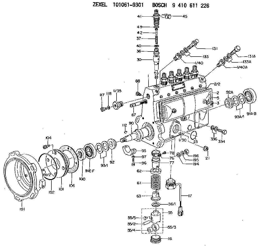
| 1. | [1] | 131073-7920 | PUMP HOUSING |
| 1/30. | [3] | 029040-6020 | STUD |
| 1/35. | [1] | 134419-0000 | ADAPTOR |
| 1/40. | [1] | 131002-4500 | ADAPTOR |
| 1/40A. | [1] | 131002-7000 | ADAPTOR |
| 2. | [1] | 131028-6020 | COVER |
| 2/2. | [1] | 131011-0800 | GASKET |
| 3. | [2] | 131017-1000 | FLAT-HEAD SCREW |
| 5. | [2] | 029340-6020 | GASKET D10&6.5T1.00 |
| 16. | [5] | 131034-1401 | CAPSULE |
| 17. | [1] | 131034-3900 | PULSE GENERATOR |
| 21. | [3] | 139206-0400 | UNION NUT |
| 23. | [1] | 029633-1010 | O-RING |
| 30. | [6] | 131152-4820 | PLUNGER-AND-BARREL ASSY |
| 36. | [6] | 131160-5120 | DELIVERY-VALVE ASSEMBLY |
| 37. | [6] | 131112-2900 | COILED SPRING |
| 40. | [6] | 131115-1600 | GASKET |
| 41. | [6] | 131116-7600 | FITTING |
| 42. | [6] | 131117-3700 | FILLER PIECE T4.5 |
| 45. | [3] | 131122-0320 | PLATE |
| 49. | [6] | 029632-0030 | O-RING |
| 55. | [6] | 131200-2820 | TAPPET |
| 55/2. | [1] | 131203-0800 | BEARING PIN |
| 55/3. | [1] | 131204-1000 | ROLLER |
| 55/4. | [1] | 131205-0500 | BUSHING |
| 55/5. | [1] | 131206-0200 | SLIDER |
| 56/1. | [0] | 029311-0020 | SHIM D19&10T0.30 |
| 56/1. | [0] | 029311-0030 | SHIM D19&10T0.40 |
| 56/1. | [0] | 029311-0040 | SHIM D19&10T0.50 |
| 56/1. | [0] | 029311-0050 | SHIM D19&10T0.6 |
| 56/1. | [0] | 029311-0060 | SHIM D19&10T0.7 |
| 56/1. | [0] | 029311-0070 | SHIM D19&10T0.8 |
| 56/1. | [0] | 029311-0080 | SHIM D19&10T0.9 |
| 56/1. | [0] | 029311-0090 | SHIM D19&10T1 |
| 56/1. | [0] | 029311-0110 | SHIM D19&10T1.1 |
| 56/1. | [0] | 029311-0120 | SHIM D19&10T1.2 |
| 56/1. | [0] | 029311-0130 | SHIM D19&10T1.3 |
| 56/1. | [0] | 029311-0140 | SHIM D19&10T1.4 |
| 56/1. | [0] | 029311-0270 | SHIM D19&10T0.55 |
| 56/1. | [0] | 029311-0280 | SHIM D19&10T0.65 |
| 56/1. | [0] | 029311-0290 | SHIM D19&10T0.75 |
| 56/1. | [0] | 029311-0310 | SHIM D19&10T0.85 |
| 56/1. | [0] | 029311-0320 | SHIM D19&10T0.95 |
| 56/1. | [0] | 029311-0330 | SHIM D19&10T1.05 |
| 56/1. | [0] | 029311-0340 | SHIM D19&10T1.15 |
| 56/1. | [0] | 029311-0350 | SHIM D19&10T1.25 |
| 56/1. | [0] | 029311-0490 | SHIM D19&10T1.5 |
| 56/1. | [0] | 029311-0500 | SHIM D19&10T1.6 |
| 56/1. | [0] | 029311-0580 | SHIM D19&10T0.2 |
| 56/1. | [0] | 029311-0590 | SHIM D19&10T0.25 |
| 56/1. | [0] | 029311-0600 | SHIM D19&10T0.35 |
| 56/1. | [0] | 029311-0610 | SHIM D19&10T0.45 |
| 56/1. | [0] | 029311-0620 | SHIM D19&10T1.35 |
| 56/1. | [0] | 029311-0630 | SHIM D19&10T1.45 |
| 56/1. | [0] | 029311-0710 | SHIM D19&10T1.55 |
| 61. | [6] | 131215-2600 | COMPRESSION SPRING |
| 62. | [6] | 131216-0100 | SLOTTED WASHER |
| 63. | [6] | 131217-0200 | SLOTTED WASHER |
| 67. | [1] | 131256-0000 | CONTROL RACK |
| 68. | [1] | 131226-0300 | FLAT-HEAD SCREW |
| 76. | [6] | 131240-0100 | PINION |
| 77. | [6] | 131241-0100 | CONTROL SLEEVE |
| 78. | [6] | 131242-0100 | FLAT-HEAD SCREW |
| 90. | [1] | 131371-4000 | CAMSHAFT |
| 91A. | [1] | 016630-2030 | BEARING PLATE |
| 91B. | [1] | 028201-7020 | BEARING PLATE |
| 91E. | [1] | 016640-2030 | BEARING PLATE |
| 91F. | [1] | 028202-0020 | BEARING PLATE |
| 92. | [1] | 131302-1000 | SPACER RING |
| 92A. | [1] | 131302-0300 | SPACER RING |
| 93/1. | [0] | 029312-0220 | SHIM D27&20T0.1 |
| 93/1. | [0] | 029312-0230 | SHIM D27&20T0.12 |
| 93/1. | [0] | 029312-0240 | SHIM D27&20T0.14 |
| 93/1. | [0] | 029312-0250 | SHIM D27&20T0.16 |
| 93/1. | [0] | 029312-0260 | SHIM D27&20T0.18 |
| 93/1. | [0] | 029312-0270 | SHIM D27&20T0.5 |
| 93/1. | [0] | 029312-0290 | SHIM D27&20T0.3 |
| 93/1. | [0] | 029312-0300 | SHIM D27&20T1.0 |
| 93/1. | [0] | 139420-0400 | SHIM D27&20T0.7 |
| 93A/1. | [0] | 029311-7010 | SHIM D22&17T0.1 |
| 93A/1. | [0] | 029311-7020 | SHIM D22&17T0.12 |
| 93A/1. | [0] | 029311-7030 | SHIM D22&17T0.14 |
| 93A/1. | [0] | 029311-7040 | SHIM D22&17T0.16 |
| 93A/1. | [0] | 029311-7050 | SHIM D22&17T0.18 |
| 93A/1. | [0] | 029311-7060 | SHIM D22&17T0.5 |
| 93A/1. | [0] | 029311-7070 | SHIM D22&17T1.0 |
| 93A/1. | [0] | 029311-7090 | SHIM D22&17T0.3 |
| 93A/1. | [0] | 029311-7210 | SHIM D22&17T0.7 |
| 93A/1. | [0] | 029311-7220 | SHIM D22&17T1.4 |
| 93A/1. | [0] | 139417-0000 | SHIM D22&17T2.4 |
| 95. | [1] | 131306-1000 | BEARING SHELL |
| 96. | [2] | 029050-5010 | FLAT-HEAD SCREW M5P0.8L32 |
| 97. | [2] | 026505-0940 | GASKET |
| 100. | [1] | 029622-0190 | PACKING RING |
| 101. | [1] | 131330-1800 | COVER |
| 104. | [4] | 020006-2040 | BLEEDER SCREW M6P1L20 4T |
| 106. | [1] | 131321-1900 | GASKET |
| 112. | [1] | 029470-4030 | WOODRUFF KEY |
| 117. | [1] | 131420-0400 | BLEEDER SCREW |
| 118. | [1] | 026506-1040 | GASKET D9.9&6.2T1 |
| 131. | [1] | 131424-6220 | OVER FLOW VALVE |
| 131A. | [1] | 139814-0900 | EYE BOLT |
| 133. | [2] | 029341-4130 | GASKET D20&13.8T2* |
| 133A. | [2] | 029341-4130 | GASKET D20&13.8T2* |
| 191. | [1] | 131460-0420 | BRACKET |
| 191/2. | [4] | 029041-0300 | STUD |
| 192. | [1] | 029637-5020 | O-RING &73.5W2 |
| 194. | [4] | 014011-0140 | PLAIN WASHER D22&10.5T1.6 |
| 195. | [4] | 014111-0440 | LOCKING WASHER |
| 196. | [4] | 013021-0040 | UNION NUT M10P1.5H8 |
| 334. | [1] | 029731-0120 | EYE BOLT |
| 336. | [2] | 026510-1340 | GASKET D13.4&10.2T1 |
Cross reference number
Zexel num
Bosch num
Firm num
Name
Information:
Grounding Practices
Proper grounding for vehicle and engine electrical systems is necessary for proper vehicle performance and reliability. Improper grounding will result in uncontrolled and unreliable electrical circuit paths.Uncontrolled engine electrical circuit paths can result in damage to main bearings, crankshaft journal surfaces, and aluminum components.Uncontrolled electrical circuit paths can cause electrical noise which may degrade vehicle and radio performance.To insure proper functioning of the vehicle and engine electrical systems, an engine-to-frame ground strap with a direct path to the battery must be used. This may be provided by way of a starter motor ground, a frame to starter motor ground, or a direct frame to engine ground.In any case, an engine-to-frame ground strap must be run from the cylinder head grounding stud to the frame and negative battery post.
Cylinder Head-To-Battery (-) Ground
Alternate Cylinder Head-To-Battery (-) GroundThe cylinder head must have a wire ground to battery as shown in the above illustrations.Ground wires/straps should be combined at ground studs dedicated for ground use only. At "Every 12,500 miles (20 125 km) or 250 hours," Inspect/Check all engine grounds. All grounds should be tight and free of corrosion.All ground paths must be capable of carrying any conceivable fault currents, and an awg # 0 or larger wire is recommended for the cylinder head grounding strap.The engine alternator should be battery (-) grounded with a wire size adequate to handle full alternator charging current.
When boost starting an engine, follow the instructions in "Engine Starting" in the "Operation Section" to properly start the engine.This engine may be equipped with a 12 or 24 volt starting system. Use only equal voltage for boost starting. The use of a welder or higher voltage will damage the electrical system.
The engine has several input components which are electronic. These components require an operating voltage.Unlike many electronic systems of the past, this engine is tolerant to common external sources of electrical noise, but electro-mechanical buzzers can cause disruptions in the power supply. If electro-mechanical buzzers are used anywhere on the vehicle, it is desirable to have the engine electronics (control group, throttle position sensor, and "check engine" lamp) powered directly from the battery system through a dedicated relay, and not through a common power bus with other key switch activated devices.Engine Electrical System
The electrical system can have three separate circuits: the charging circuit, the starting circuit and the low amperage circuit. Some of the electrical system components are used in more than one circuit. The battery (batteries), circuit breaker, ammeter, cables and wires from the battery are all common in each of the circuits.The charging circuit is in operation when the engine is running. An alternator makes electricity for the charging circuit. A voltage regulator in the circuit controls the electrical output to keep the battery at full charge.The starting circuit is in operation only when the start switch is activated.The low amperage circuit and the charging circuit are both connected through the ammeter. The starting circuit is not connected through the ammeter.Charging System Components
Alternator
The alternator is