Information fuel-injection pump
BOSCH
9 410 612 177
9410612177
ZEXEL
101061-8250
1010618250
MITSUBISHI
ME727132
me727132

Rating:
Scheme ###:
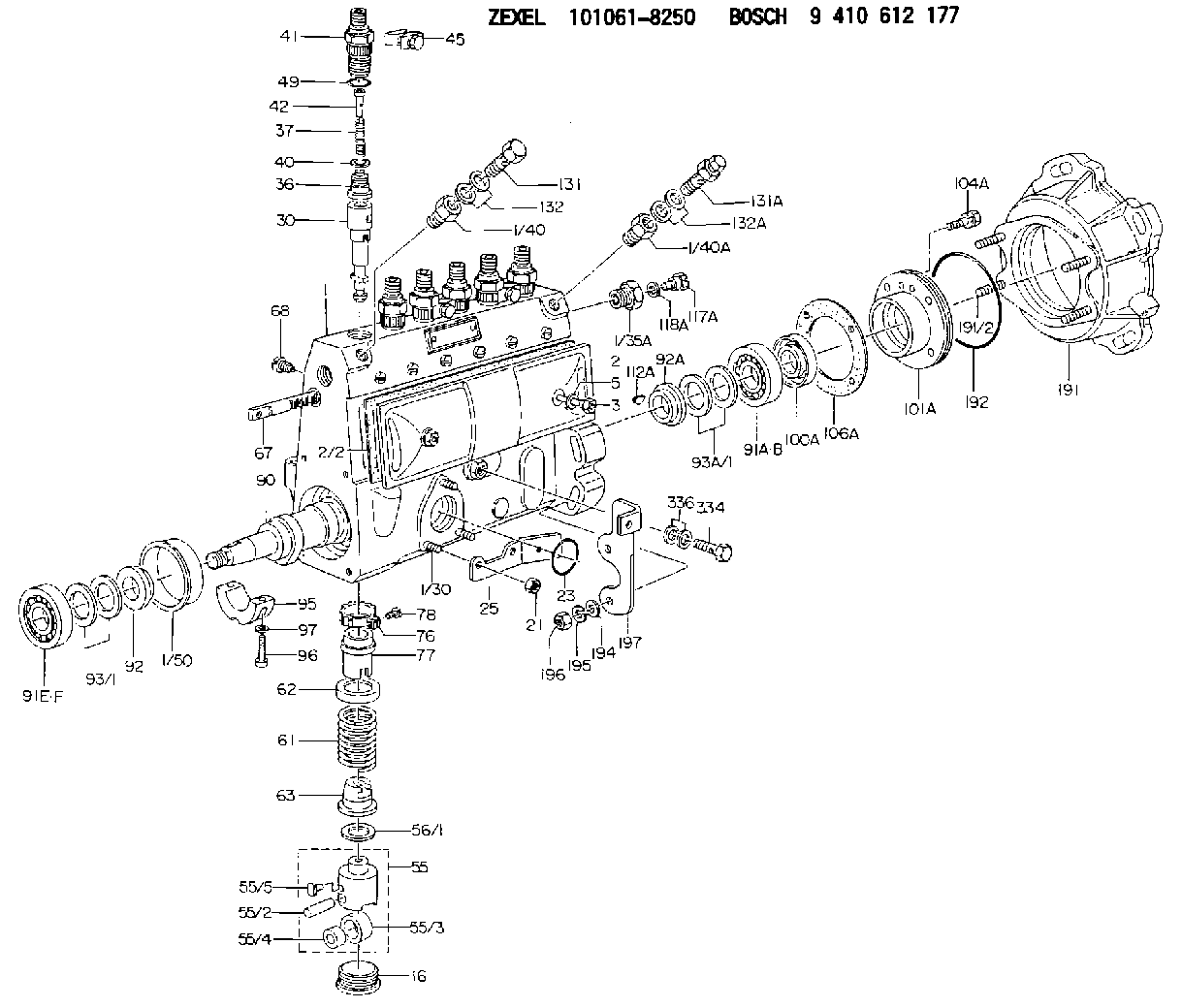
| 1. | [1] | 131076-7320 | PUMP HOUSING |
| 1/30. | [3] | 029040-6220 | STUD |
| 1/35A. | [1] | 134419-0000 | ADAPTOR |
| 1/40. | [1] | 131002-4700 | ADAPTOR |
| 1/40A. | [1] | 131002-5000 | ADAPTOR |
| 1/50. | [1] | 131311-0100 | SPACER RING |
| 2. | [1] | 131028-6020 | COVER |
| 2/2. | [1] | 131011-0800 | GASKET |
| 3. | [2] | 131017-1000 | FLAT-HEAD SCREW |
| 5. | [2] | 029340-6020 | GASKET D10&6.5T1.00 |
| 16. | [6] | 131034-1501 | CAPSULE |
| 21. | [3] | 139206-0400 | UNION NUT |
| 23. | [1] | 029633-1010 | O-RING |
| 25. | [1] | 131563-1500 | BRACKET |
| 30. | [6] | 131153-4420 | PLUNGER-AND-BARREL ASSY |
| 36. | [6] | 131160-5320 | DELIVERY-VALVE ASSEMBLY |
| 37. | [6] | 131112-5300 | COILED SPRING |
| 40. | [6] | 131115-1200 | GASKET D16&8T0.5 |
| 41. | [6] | 131116-8300 | FITTING |
| 42. | [6] | 131117-2100 | FILLER PIECE |
| 45. | [3] | 131122-0520 | PLATE |
| 49. | [6] | 029632-0070 | O-RING &20W2 |
| 55. | [6] | 131200-2720 | TAPPET |
| 55/2. | [1] | 131203-0500 | BEARING PIN |
| 55/3. | [1] | 131204-1100 | ROLLER |
| 55/4. | [1] | 131205-0600 | BUSHING |
| 55/5. | [1] | 131206-0700 | SLIDER |
| 56/1. | [0] | 029311-0020 | SHIM D19&10T0.30 |
| 56/1. | [0] | 029311-0030 | SHIM D19&10T0.40 |
| 56/1. | [0] | 029311-0040 | SHIM D19&10T0.50 |
| 56/1. | [0] | 029311-0050 | SHIM D19&10T0.6 |
| 56/1. | [0] | 029311-0060 | SHIM D19&10T0.7 |
| 56/1. | [0] | 029311-0070 | SHIM D19&10T0.8 |
| 56/1. | [0] | 029311-0080 | SHIM D19&10T0.9 |
| 56/1. | [0] | 029311-0090 | SHIM D19&10T1 |
| 56/1. | [0] | 029311-0110 | SHIM D19&10T1.1 |
| 56/1. | [0] | 029311-0120 | SHIM D19&10T1.2 |
| 56/1. | [0] | 029311-0130 | SHIM D19&10T1.3 |
| 56/1. | [0] | 029311-0140 | SHIM D19&10T1.4 |
| 56/1. | [0] | 029311-0270 | SHIM D19&10T0.55 |
| 56/1. | [0] | 029311-0280 | SHIM D19&10T0.65 |
| 56/1. | [0] | 029311-0290 | SHIM D19&10T0.75 |
| 56/1. | [0] | 029311-0310 | SHIM D19&10T0.85 |
| 56/1. | [0] | 029311-0320 | SHIM D19&10T0.95 |
| 56/1. | [0] | 029311-0330 | SHIM D19&10T1.05 |
| 56/1. | [0] | 029311-0340 | SHIM D19&10T1.15 |
| 56/1. | [0] | 029311-0350 | SHIM D19&10T1.25 |
| 56/1. | [0] | 029311-0490 | SHIM D19&10T1.5 |
| 56/1. | [0] | 029311-0500 | SHIM D19&10T1.6 |
| 56/1. | [0] | 029311-0580 | SHIM D19&10T0.2 |
| 56/1. | [0] | 029311-0590 | SHIM D19&10T0.25 |
| 56/1. | [0] | 029311-0600 | SHIM D19&10T0.35 |
| 56/1. | [0] | 029311-0610 | SHIM D19&10T0.45 |
| 56/1. | [0] | 029311-0620 | SHIM D19&10T1.35 |
| 56/1. | [0] | 029311-0630 | SHIM D19&10T1.45 |
| 56/1. | [0] | 029311-0710 | SHIM D19&10T1.55 |
| 61. | [6] | 131215-2100 | COMPRESSION SPRING |
| 62. | [6] | 131216-0400 | SLOTTED WASHER |
| 63. | [6] | 131217-0600 | SLOTTED WASHER |
| 67. | [1] | 131256-0000 | CONTROL RACK |
| 68. | [1] | 131226-0300 | FLAT-HEAD SCREW |
| 76. | [6] | 131240-0100 | PINION |
| 77. | [6] | 131241-0500 | CONTROL SLEEVE |
| 78. | [6] | 131242-0100 | FLAT-HEAD SCREW |
| 90. | [1] | 131375-0600 | CAMSHAFT |
| 91A. | [1] | 016640-2030 | BEARING PLATE |
| 91B. | [1] | 028202-0020 | BEARING PLATE |
| 91E. | [1] | 016630-2030 | BEARING PLATE |
| 91F. | [1] | 028201-7020 | BEARING PLATE |
| 92. | [1] | 131302-0400 | SPACER RING |
| 92A. | [1] | 131302-1000 | SPACER RING |
| 93/1. | [0] | 029311-7010 | SHIM D22&17T0.1 |
| 93/1. | [0] | 029311-7020 | SHIM D22&17T0.12 |
| 93/1. | [0] | 029311-7030 | SHIM D22&17T0.14 |
| 93/1. | [0] | 029311-7040 | SHIM D22&17T0.16 |
| 93/1. | [0] | 029311-7050 | SHIM D22&17T0.18 |
| 93/1. | [0] | 029311-7060 | SHIM D22&17T0.5 |
| 93/1. | [0] | 029311-7070 | SHIM D22&17T1.0 |
| 93/1. | [0] | 029311-7090 | SHIM D22&17T0.3 |
| 93/1. | [0] | 029311-7210 | SHIM D22&17T0.7 |
| 93/1. | [0] | 029311-7220 | SHIM D22&17T1.4 |
| 93/1. | [0] | 139417-0000 | SHIM D22&17T2.4 |
| 93A/1. | [0] | 029312-0220 | SHIM D27&20T0.1 |
| 93A/1. | [0] | 029312-0230 | SHIM D27&20T0.12 |
| 93A/1. | [0] | 029312-0240 | SHIM D27&20T0.14 |
| 93A/1. | [0] | 029312-0250 | SHIM D27&20T0.16 |
| 93A/1. | [0] | 029312-0260 | SHIM D27&20T0.18 |
| 93A/1. | [0] | 029312-0270 | SHIM D27&20T0.5 |
| 93A/1. | [0] | 029312-0290 | SHIM D27&20T0.3 |
| 93A/1. | [0] | 029312-0300 | SHIM D27&20T1.0 |
| 93A/1. | [0] | 139420-0400 | SHIM D27&20T0.7 |
| 95. | [1] | 131305-0600 | BEARING SHELL |
| 96. | [2] | 139105-0200 | FLAT-HEAD SCREW |
| 97. | [2] | 026505-0940 | GASKET |
| 100A. | [1] | 029622-0190 | PACKING RING |
| 101A. | [1] | 131330-1800 | COVER |
| 104A. | [4] | 020006-2040 | BLEEDER SCREW M6P1L20 4T |
| 106A. | [1] | 131321-1900 | GASKET |
| 112A. | [1] | 029470-4030 | WOODRUFF KEY |
| 117A. | [1] | 131420-0400 | BLEEDER SCREW |
| 118A. | [1] | 026506-1040 | GASKET D9.9&6.2T1 |
| 131. | [1] | 139814-0900 | EYE BOLT |
| 131A. | [1] | 131424-5520 | OVER FLOW VALVE |
| 132. | [2] | 029341-4130 | GASKET D20&13.8T2* |
| 132A. | [2] | 029341-4130 | GASKET D20&13.8T2* |
| 191. | [1] | 131460-2020 | BRACKET |
| 191/2. | [4] | 029041-0300 | STUD |
| 192. | [1] | 029637-5020 | O-RING &73.5W2 |
| 194. | [2] | 139310-0000 | PLAIN WASHER |
| 195. | [4] | 014111-0440 | LOCKING WASHER |
| 196. | [4] | 013021-0040 | UNION NUT M10P1.5H8 |
| 197. | [1] | 131563-2600 | BRACKET |
| 334. | [1] | 029731-0120 | EYE BOLT |
| 336. | [2] | 026510-1340 | GASKET D13.4&10.2T1 |
Cross reference number
Zexel num
Bosch num
Firm num
Name
Information:
2. Remove bolts (3) from cover (1). Remove bolt and washer (2) and remove tube and adapter (4). 3. Remove adapter (5) from tube (4). Remove four O-ring seals (6) from tube (4). 4. Remove four bolts (7), elbow (9) and two adapters (8). 5. Remove four bolts (11), elbow (12), two adapters (10) and pipe (13). 6. Remove twenty-four bolts (15). Remove aftercooler cover (14). 7. Remove aftercooler core (16) from aftercooler housing (17). 8. Remove O-ring seals (19) and gaskets (18) if necessary. The following steps are for the installation of the aftercooler core.9. Clean and inspect all parts. Make a replacement of the parts that are worn or damaged. Lubricate O-ring seals with clean oil at assembly.10. Install O-ring seals (19). Fasten gaskets (18) to both sides of the aftercooler core flange with 5H2471 Cement.11. Install aftercooler core (16) in the aftercooler housing with the end that has the identification "Jacket Water, Fresh Air" or "Treated Water, Fresh Air" toward the water inlet end of the aftercooler housing.12. Install cover (14) on aftercooler housing (17).
To prevent damage to the aftercooler core, tighten the bolts that hold the aftercooler core before tightening the bolts that hold the adapters.
13. Tighten the aftercooler core cover bolts to a torque of 25 7 N m (18 5 lb. ft.). Tighten the bolts again after the engine is operated to a torque of 25 7 N m (18 5 lb. ft.).14. Install the gaskets and adapters (10) on the aftercooler housing. 15. Put O-ring seals (20) on pipe (13) and install pipe (13) into elbow (21).16. Install elbow (12) on pipe (13). Put a gasket between the adapters and elbow (12). Install bolts (11).17. Install gaskets and adapters (8) on the aftercooler housing. Install a gasket and elbow (9). Install bolts (7).18. Install O-ring seals (6) on tube (4). Install adapter (5) on tube (4).19. Install the gasket, adapter and tube (4). Install washer and bolt (2). Install the gasket and cover (1). Tighten bolts (3) to 23 4 N m (17 3 lb. ft.).20. Fill the engine with oil to the correct level. See the Maintenance Manual.