Information fuel-injection pump
BOSCH
9 410 612 294
9410612294
ZEXEL
101061-8141
1010618141
MITSUBISHI
ME730325
me730325

Rating:
Scheme ###:
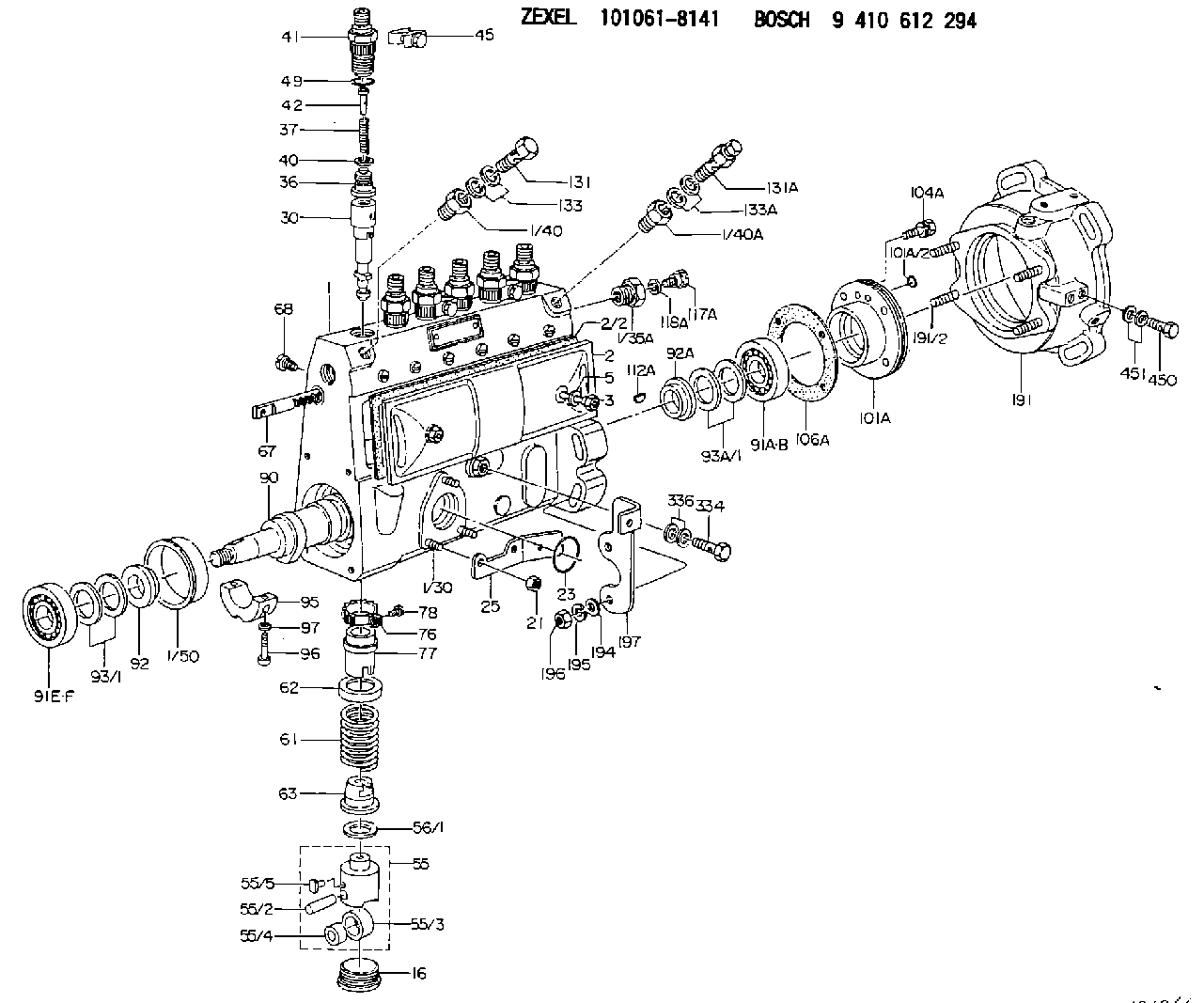
| 1. | [1] | 131076-6420 | PUMP HOUSING |
| 1/30. | [3] | 029040-6220 | STUD |
| 1/35A. | [1] | 134419-0000 | ADAPTOR |
| 1/40. | [1] | 131002-4900 | ADAPTOR |
| 1/40A. | [1] | 131002-5000 | ADAPTOR |
| 1/50. | [1] | 131311-0100 | SPACER RING |
| 2. | [1] | 131028-6020 | COVER |
| 2/2. | [1] | 131011-0800 | GASKET |
| 3. | [2] | 131017-1000 | FLAT-HEAD SCREW |
| 5. | [2] | 029340-6020 | GASKET D10&6.5T1.00 |
| 16. | [6] | 131034-1501 | CAPSULE |
| 21. | [3] | 139206-0400 | UNION NUT |
| 23. | [1] | 029633-1010 | O-RING |
| 25. | [1] | 131563-1500 | BRACKET |
| 30. | [6] | 131153-0420 | PLUNGER-AND-BARREL ASSY |
| 36. | [6] | 131110-8820 | DELIVERY-VALVE ASSEMBLY |
| 37. | [6] | 131112-5100 | COILED SPRING |
| 40. | [6] | 131115-1200 | GASKET D16&8T0.5 |
| 41. | [6] | 131116-8300 | FITTING |
| 42. | [6] | 131117-2100 | FILLER PIECE |
| 45. | [3] | 131122-0520 | PLATE |
| 49. | [6] | 029632-0070 | O-RING &20W2 |
| 55. | [6] | 131200-2720 | TAPPET |
| 55/2. | [1] | 131203-0500 | BEARING PIN |
| 55/3. | [1] | 131204-1100 | ROLLER |
| 55/4. | [1] | 131205-0600 | BUSHING |
| 55/5. | [1] | 131206-0700 | SLIDER |
| 56/1. | [0] | 029311-0020 | SHIM D19&10T0.30 |
| 56/1. | [0] | 029311-0030 | SHIM D19&10T0.40 |
| 56/1. | [0] | 029311-0040 | SHIM D19&10T0.50 |
| 56/1. | [0] | 029311-0050 | SHIM D19&10T0.6 |
| 56/1. | [0] | 029311-0060 | SHIM D19&10T0.7 |
| 56/1. | [0] | 029311-0070 | SHIM D19&10T0.8 |
| 56/1. | [0] | 029311-0080 | SHIM D19&10T0.9 |
| 56/1. | [0] | 029311-0090 | SHIM D19&10T1 |
| 56/1. | [0] | 029311-0110 | SHIM D19&10T1.1 |
| 56/1. | [0] | 029311-0120 | SHIM D19&10T1.2 |
| 56/1. | [0] | 029311-0130 | SHIM D19&10T1.3 |
| 56/1. | [0] | 029311-0140 | SHIM D19&10T1.4 |
| 56/1. | [0] | 029311-0270 | SHIM D19&10T0.55 |
| 56/1. | [0] | 029311-0280 | SHIM D19&10T0.65 |
| 56/1. | [0] | 029311-0290 | SHIM D19&10T0.75 |
| 56/1. | [0] | 029311-0310 | SHIM D19&10T0.85 |
| 56/1. | [0] | 029311-0320 | SHIM D19&10T0.95 |
| 56/1. | [0] | 029311-0330 | SHIM D19&10T1.05 |
| 56/1. | [0] | 029311-0340 | SHIM D19&10T1.15 |
| 56/1. | [0] | 029311-0350 | SHIM D19&10T1.25 |
| 56/1. | [0] | 029311-0490 | SHIM D19&10T1.5 |
| 56/1. | [0] | 029311-0500 | SHIM D19&10T1.6 |
| 56/1. | [0] | 029311-0580 | SHIM D19&10T0.2 |
| 56/1. | [0] | 029311-0590 | SHIM D19&10T0.25 |
| 56/1. | [0] | 029311-0600 | SHIM D19&10T0.35 |
| 56/1. | [0] | 029311-0610 | SHIM D19&10T0.45 |
| 56/1. | [0] | 029311-0620 | SHIM D19&10T1.35 |
| 56/1. | [0] | 029311-0630 | SHIM D19&10T1.45 |
| 56/1. | [0] | 029311-0710 | SHIM D19&10T1.55 |
| 61. | [6] | 131215-2100 | COMPRESSION SPRING |
| 62. | [6] | 131216-0400 | SLOTTED WASHER |
| 63. | [6] | 131217-0600 | SLOTTED WASHER |
| 67. | [1] | 131256-0000 | CONTROL RACK |
| 68. | [1] | 131226-0300 | FLAT-HEAD SCREW |
| 76. | [6] | 131240-0100 | PINION |
| 77. | [6] | 131241-0500 | CONTROL SLEEVE |
| 78. | [6] | 131242-0100 | FLAT-HEAD SCREW |
| 90. | [1] | 131375-0600 | CAMSHAFT |
| 91A. | [1] | 016640-2030 | BEARING PLATE |
| 91B. | [1] | 028202-0020 | BEARING PLATE |
| 91E. | [1] | 016630-2030 | BEARING PLATE |
| 91F. | [1] | 028201-7020 | BEARING PLATE |
| 92. | [1] | 131302-0400 | SPACER RING |
| 92A. | [1] | 131302-1000 | SPACER RING |
| 93/1. | [0] | 029311-7010 | SHIM D22&17T0.1 |
| 93/1. | [0] | 029311-7020 | SHIM D22&17T0.12 |
| 93/1. | [0] | 029311-7030 | SHIM D22&17T0.14 |
| 93/1. | [0] | 029311-7040 | SHIM D22&17T0.16 |
| 93/1. | [0] | 029311-7050 | SHIM D22&17T0.18 |
| 93/1. | [0] | 029311-7060 | SHIM D22&17T0.5 |
| 93/1. | [0] | 029311-7070 | SHIM D22&17T1.0 |
| 93/1. | [0] | 029311-7090 | SHIM D22&17T0.3 |
| 93/1. | [0] | 029311-7210 | SHIM D22&17T0.7 |
| 93/1. | [0] | 029311-7220 | SHIM D22&17T1.4 |
| 93/1. | [0] | 139417-0000 | SHIM D22&17T2.4 |
| 93A/1. | [0] | 029312-0220 | SHIM D27&20T0.1 |
| 93A/1. | [0] | 029312-0230 | SHIM D27&20T0.12 |
| 93A/1. | [0] | 029312-0240 | SHIM D27&20T0.14 |
| 93A/1. | [0] | 029312-0250 | SHIM D27&20T0.16 |
| 93A/1. | [0] | 029312-0260 | SHIM D27&20T0.18 |
| 93A/1. | [0] | 029312-0270 | SHIM D27&20T0.5 |
| 93A/1. | [0] | 029312-0290 | SHIM D27&20T0.3 |
| 93A/1. | [0] | 029312-0300 | SHIM D27&20T1.0 |
| 93A/1. | [0] | 139420-0400 | SHIM D27&20T0.7 |
| 95. | [1] | 131305-0600 | BEARING SHELL |
| 96. | [2] | 139105-0200 | FLAT-HEAD SCREW |
| 97. | [2] | 026505-0940 | GASKET |
| 101A. | [1] | 131330-6120 | COVER |
| 101A/2. | [2] | 016520-7110 | O-RING |
| 104A. | [4] | 029000-6650 | BLEEDER SCREW |
| 106A. | [1] | 131321-1900 | GASKET |
| 112A. | [1] | 029470-4030 | WOODRUFF KEY |
| 117A. | [1] | 131420-0400 | BLEEDER SCREW |
| 118A. | [1] | 026506-1040 | GASKET D9.9&6.2T1 |
| 131. | [1] | 139814-0900 | EYE BOLT |
| 131A. | [1] | 131424-5520 | OVER FLOW VALVE |
| 133. | [2] | 029341-4130 | GASKET D20&13.8T2* |
| 133A. | [2] | 029341-4130 | GASKET D20&13.8T2* |
| 191. | [1] | 131460-3120 | BRACKET |
| 191/2. | [4] | 029041-0300 | STUD |
| 194. | [2] | 139310-0000 | PLAIN WASHER |
| 195. | [4] | 014111-0440 | LOCKING WASHER |
| 196. | [4] | 013021-0040 | UNION NUT M10P1.5H8 |
| 197. | [1] | 131563-2600 | BRACKET |
| 334. | [1] | 029731-0120 | EYE BOLT |
| 336. | [2] | 026510-1340 | GASKET D13.4&10.2T1 |
| 450. | [2] | 139812-1200 | EYE BOLT |
| 451. | [4] | 029341-2140 | GASKET |
Cross reference number
Zexel num
Bosch num
Firm num
Name
Information:
1. Remove fuel line (1) and (3) from the fuel transfer pump.2. Put caps in the fuel line openings to prevent fuel system contamination.3. Remove bolts (2), and remove fuel transfer pump (4). Check the condition of the O-ring seal on the fuel transfer pump. If necessary, make a replacement. The following steps are for installtion of the fuel transfer pump.4. Be sure the O-ring seal is in position on the fuel transfer pump. Put clean engine oil on the O-ring seal.5. Put fuel transfer pump (4) in position, and install the bolts that hold it in place.6. Remove the caps from the fuel line openings, and install fuel lines (1) and (3).Disassemble Fuel Transfer Pump
Start By:a. remove fuel transfer pump 1. Remove seal (1) from the fuel transfer pump.
Cover (2) is under spring tension. Remove the bolts that hold cover (2) slowly to prevent injury.
2. Remove bolts (3) and cover (2) from the housing. 3. Remove seals (4) and valve (5) from cover (2). 4. Remove spring (6) from the piston.
Mark the orientation of valve (8) as to its location in the housing.
5. Remove washer (7), valve (8) and the seal from the housing. 6. Remove piston (9) and sleeve (10) from the housing. 7. Remove seal (11) from sleeve (12). 8. Remove guide and tappet assembly (13) from the housing. 9. Remove seal (14) from guide (15).
If tappet (17) or the guide are damaged or worn, they must be replaced as a unit.
10. Remove ring (16) from tappet (17) and the tappet from guide (15). 11. Remove the bolts and cover (18) from the housing. 12. Remove seal (19) from cover (18). 13. Remove valve (20) from the housing if necessary.Assemble Fuel Transfer Pump
1. Install valve (20) in housing as shown. 2. Put clean fuel on seal (19), and install it on cover (18).3. Install cover (18) on the housing.
The tappet and guide must be serviced as a unit.
4. Install tappet (17) in guide (15). Install ring (16) on tappet (17) to hold the tappet in the guide. 5. Put clean fuel on seal (14), and install it on guide and tappet assembly (13).6. Install guide and tappet assembly (13) in the housing as shown. 7. Put clean fuel on seal (11), and install it on sleeve (12).8. Install sleeve (12) in the housing. 9. Install piston (9) in the housing. 10. Install seal, valve (8) and washer (7) in the housing as shown. Be sure valve (8) is the correct position in the housing. 11. Install spring (6) in the piston. 12. Install valve (5) in cover (2) as shown.13. Put clean fuel on seals (4), and put them in position on cover (2).14. Install cover (2) on the housing. 15. Put seal (1) in position on the fuel transfer pump.16. Install the fuel transfer pump on the fuel injection pump housing.End By:a. install fuel transfer pump