Information fuel-injection pump
BOSCH
9 410 612 763
9410612763
ZEXEL
101060-9830
1010609830
MITSUBISHI
ME717246
me717246
Rating:
Scheme ###:
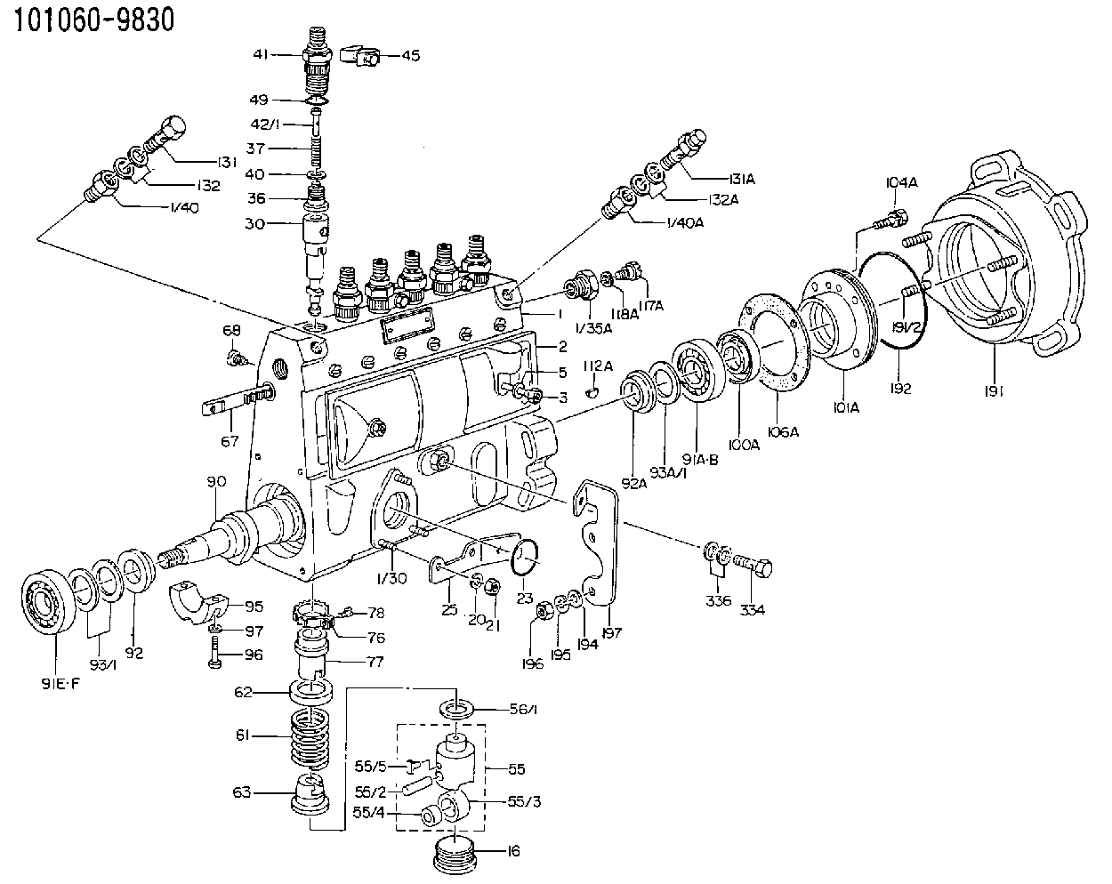
| 1. | [1] | 131072-5820 | PUMP HOUSING |
| 1/30. | [3] | 029040-6220 | STUD |
| 1/35A. | [1] | 134419-0000 | ADAPTOR |
| 1/40. | [1] | 131423-0900 | ADAPTOR |
| 1/40A. | [1] | 131423-1300 | ADAPTOR |
| 2. | [1] | 131028-6020 | COVER |
| 2/2. | [1] | 131011-0800 | GASKET |
| 3. | [2] | 131017-1000 | FLAT-HEAD SCREW |
| 5. | [2] | 029340-6020 | GASKET D10&6.5T1.00 |
| 16. | [6] | 131034-1401 | CAPSULE |
| 21. | [3] | 139206-0400 | UNION NUT |
| 23. | [1] | 029633-1010 | O-RING |
| 25. | [1] | 131563-1500 | BRACKET |
| 30. | [6] | 131152-5220 | PLUNGER-AND-BARREL ASSY |
| 36. | [6] | 131160-2620 | DELIVERY-VALVE ASSEMBLY |
| 37. | [6] | 131112-4700 | COMPRESSION SPRING |
| 40. | [6] | 131115-1600 | GASKET |
| 41. | [6] | 131116-7600 | FITTING |
| 42/1. | [1] | 131117-3500 | FILLER PIECE T4.1 |
| 42/1. | [1] | 131117-3600 | FILLER PIECE T4.3 |
| 42/1. | [1] | 131117-3700 | FILLER PIECE T4.5 |
| 42/1. | [1] | 131117-3800 | FILLER PIECE T4.7 |
| 42/1. | [1] | 131117-3900 | FILLER PIECE T4.9 |
| 42/1. | [1] | 131117-4100 | FILLER PIECE T3.9 |
| 45. | [3] | 131122-0320 | PLATE |
| 49. | [6] | 029632-0030 | O-RING |
| 55. | [6] | 131200-2820 | TAPPET |
| 55/2. | [1] | 131203-0800 | BEARING PIN |
| 55/3. | [1] | 131204-1000 | ROLLER |
| 55/4. | [1] | 131205-0500 | BUSHING |
| 55/5. | [1] | 131206-0200 | SLIDER |
| 56/1. | [0] | 029311-0020 | SHIM D19&10T0.30 |
| 56/1. | [0] | 029311-0030 | SHIM D19&10T0.40 |
| 56/1. | [0] | 029311-0040 | SHIM D19&10T0.50 |
| 56/1. | [0] | 029311-0050 | SHIM D19&10T0.6 |
| 56/1. | [0] | 029311-0060 | SHIM D19&10T0.7 |
| 56/1. | [0] | 029311-0070 | SHIM D19&10T0.8 |
| 56/1. | [0] | 029311-0080 | SHIM D19&10T0.9 |
| 56/1. | [0] | 029311-0090 | SHIM D19&10T1 |
| 56/1. | [0] | 029311-0110 | SHIM D19&10T1.1 |
| 56/1. | [0] | 029311-0120 | SHIM D19&10T1.2 |
| 56/1. | [0] | 029311-0130 | SHIM D19&10T1.3 |
| 56/1. | [0] | 029311-0140 | SHIM D19&10T1.4 |
| 56/1. | [0] | 029311-0270 | SHIM D19&10T0.55 |
| 56/1. | [0] | 029311-0280 | SHIM D19&10T0.65 |
| 56/1. | [0] | 029311-0290 | SHIM D19&10T0.75 |
| 56/1. | [0] | 029311-0310 | SHIM D19&10T0.85 |
| 56/1. | [0] | 029311-0320 | SHIM D19&10T0.95 |
| 56/1. | [0] | 029311-0330 | SHIM D19&10T1.05 |
| 56/1. | [0] | 029311-0340 | SHIM D19&10T1.15 |
| 56/1. | [0] | 029311-0350 | SHIM D19&10T1.25 |
| 56/1. | [0] | 029311-0490 | SHIM D19&10T1.5 |
| 56/1. | [0] | 029311-0500 | SHIM D19&10T1.6 |
| 56/1. | [0] | 029311-0580 | SHIM D19&10T0.2 |
| 56/1. | [0] | 029311-0590 | SHIM D19&10T0.25 |
| 56/1. | [0] | 029311-0600 | SHIM D19&10T0.35 |
| 56/1. | [0] | 029311-0610 | SHIM D19&10T0.45 |
| 56/1. | [0] | 029311-0620 | SHIM D19&10T1.35 |
| 56/1. | [0] | 029311-0630 | SHIM D19&10T1.45 |
| 56/1. | [0] | 029311-0710 | SHIM D19&10T1.55 |
| 61. | [6] | 131215-2300 | COMPRESSION SPRING |
| 62. | [6] | 131216-0100 | SLOTTED WASHER |
| 63. | [6] | 131217-0200 | SLOTTED WASHER |
| 67. | [1] | 131256-0000 | CONTROL RACK |
| 68. | [1] | 131226-0300 | FLAT-HEAD SCREW |
| 76. | [6] | 131240-0100 | PINION |
| 77. | [6] | 131241-0100 | CONTROL SLEEVE |
| 78. | [6] | 131242-0100 | FLAT-HEAD SCREW |
| 90. | [1] | 131371-2500 | CAMSHAFT |
| 91A. | [1] | 016640-2030 | BEARING PLATE |
| 91B. | [1] | 028202-0020 | BEARING PLATE |
| 91E. | [1] | 016630-2030 | BEARING PLATE |
| 91F. | [1] | 028201-7020 | BEARING PLATE |
| 92. | [1] | 131302-0400 | SPACER RING |
| 92A. | [1] | 131302-1000 | SPACER RING |
| 93/1. | [0] | 029311-7010 | SHIM D22&17T0.1 |
| 93/1. | [0] | 029311-7020 | SHIM D22&17T0.12 |
| 93/1. | [0] | 029311-7030 | SHIM D22&17T0.14 |
| 93/1. | [0] | 029311-7040 | SHIM D22&17T0.16 |
| 93/1. | [0] | 029311-7050 | SHIM D22&17T0.18 |
| 93/1. | [0] | 029311-7060 | SHIM D22&17T0.5 |
| 93/1. | [0] | 029311-7070 | SHIM D22&17T1.0 |
| 93/1. | [0] | 029311-7090 | SHIM D22&17T0.3 |
| 93/1. | [0] | 029311-7210 | SHIM D22&17T0.7 |
| 93/1. | [0] | 029311-7220 | SHIM D22&17T1.4 |
| 93/1. | [0] | 139417-0000 | SHIM D22&17T2.4 |
| 93A/1. | [0] | 029312-0220 | SHIM D27&20T0.1 |
| 93A/1. | [0] | 029312-0230 | SHIM D27&20T0.12 |
| 93A/1. | [0] | 029312-0240 | SHIM D27&20T0.14 |
| 93A/1. | [0] | 029312-0250 | SHIM D27&20T0.16 |
| 93A/1. | [0] | 029312-0260 | SHIM D27&20T0.18 |
| 93A/1. | [0] | 029312-0270 | SHIM D27&20T0.5 |
| 93A/1. | [0] | 029312-0290 | SHIM D27&20T0.3 |
| 93A/1. | [0] | 029312-0300 | SHIM D27&20T1.0 |
| 93A/1. | [0] | 139420-0400 | SHIM D27&20T0.7 |
| 95. | [1] | 131306-1000 | BEARING SHELL |
| 96. | [2] | 029050-5010 | FLAT-HEAD SCREW M5P0.8L32 |
| 97. | [2] | 026505-0940 | GASKET |
| 100A. | [1] | 029622-0190 | PACKING RING |
| 101A. | [1] | 131330-1800 | COVER |
| 104A. | [4] | 020006-2040 | BLEEDER SCREW M6P1L20 4T |
| 106A. | [1] | 131321-1900 | GASKET |
| 112A. | [1] | 029470-4030 | WOODRUFF KEY |
| 117A. | [1] | 131420-0400 | BLEEDER SCREW |
| 118A. | [1] | 026506-1040 | GASKET D9.9&6.2T1 |
| 131. | [1] | 139814-0900 | EYE BOLT |
| 131A. | [1] | 131424-5520 | OVER FLOW VALVE |
| 132. | [2] | 029341-4130 | GASKET D20&13.8T2* |
| 132A. | [2] | 029341-4130 | GASKET D20&13.8T2* |
| 191. | [1] | 131460-2020 | BRACKET |
| 191/2. | [4] | 029041-0300 | STUD |
| 192. | [1] | 029637-5020 | O-RING &73.5W2 |
| 194. | [2] | 139310-0000 | PLAIN WASHER |
| 195. | [4] | 014111-0440 | LOCKING WASHER |
| 196. | [4] | 013021-0040 | UNION NUT M10P1.5H8 |
| 197. | [1] | 131563-2600 | BRACKET |
| 334. | [1] | 029731-0120 | EYE BOLT |
| 336. | [2] | 026510-1340 | GASKET D13.4&10.2T1 |
Include in #2:
105856-4560
as _
Cross reference number
Zexel num
Bosch num
Firm num
Name
Information:
Start By:a. remove timing gear coverb. remove flywheel housingc. remove pistons and connecting rod assembliesd. remove crankshaft rear seal and wear sleevee. remove crankshaft front seal and wear sleeve Check the bearing caps for a number as to their location. If a number can be seen, put a number on the left side of the cylinder block and bearing cap. 1. Remove bolts (1) that hold main bearing caps (2) to the block, and remove main bearing caps (2). 2. Install one of the bolts from the front pulley in each end of the crankshaft.3. Fasten a hoist to the crankshaft (3), and remove crankshaft (3) from the block. The weight is 159 kg (350 lb.). If new main bearings are not to be installed, keep old bearings with identification as to their location in cylinder block. 4. Use tooling (A) to remove the crankshaft gear.5. Use tooling (B) if necessary to remove the dowel and the pin.Install Crankshaft
If the crankshaft journals and bores for the block and rods were measured at disassembly and found to be within specifications, no further checks are necessary. However, if the serviceman still wants to measure the bearing clearances, Plastigage is recommended. Lead wire, shim stock or use of a dial bore gauge can damage the bearing surface.
The servicemen must be very careful to use Plastigage, tool (B) correctly. The following points must be remembered:...Make sure that the backs of the bearings and the bores are clean and dry....Make sure that the bearing locking tabs are properly seated in their slots....The crankshaft must be free of oil where the Plastigage touches it....If the main bearing clearances are checked with the engine upright or on its side, the crankshaft must be supported. Use a jack under an adjacent crankshaft counterweight and hold the crankshaft against the crown of the bearing. If the crankshaft is not supported, the weight of the crankshaft will cause incorrect readings....Put a piece of Plastigage on the crown of the bearing half that is in the cap. Do not allow the Plastigage to extend over the edge of the bearing....Install the bearing cap using the correct torque-turn specifications. Do not use an impact wrench. Be careful not to dislodge the bearing when the cap is installed....Do not turn the crankshaft with the Plastigage installed....Carefully remove the cap but do not remove the Plastigage. Measure the width of the Plastigage while it is in the bearing cap or on the crankshaft journal. Do this by using the correct scale on the package. Record the measurements....Remove the Plastigage before reinstalling the cap.When using Plastigage, the readings can sometimes be unclear. For example, all parts of the Plastigage are not the same width. Measure the major widths to make sure that they are within the specification range. Also, experience has shown that when checking clearances tighter than 0.10 mm (.004") the readings may be low by 0.013 to 0.025 mm (.0005 to .0010"). Out-of-round journals can give faulty readings. Also, journal taper