Information fuel-injection pump
BOSCH
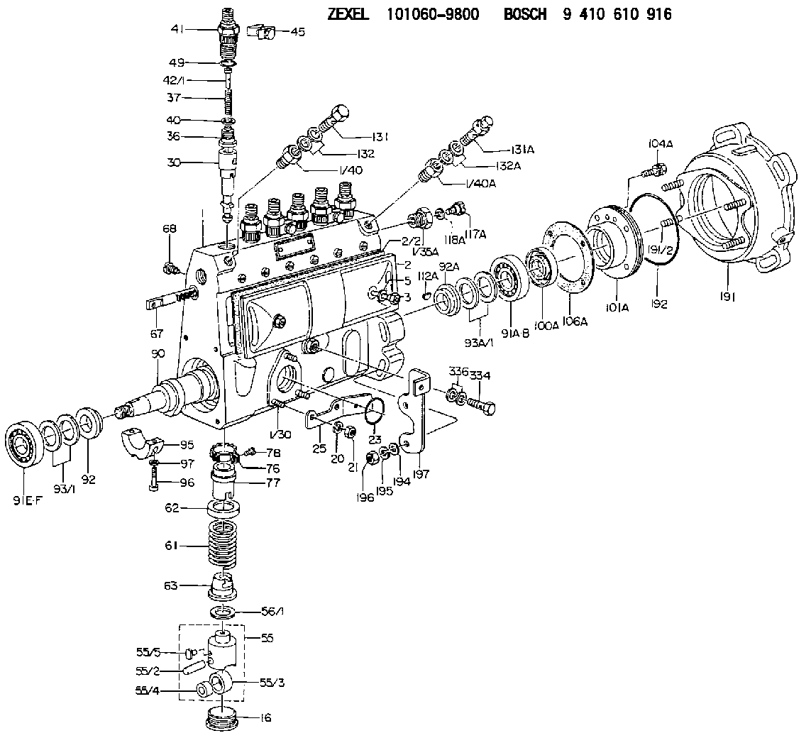
9 410 610 916
9410610916
ZEXEL
101060-9800
1010609800
MITSUBISHI
ME717243
me717243
Rating:
Scheme ###:
| 1. | [1] | 131072-5720 | PUMP HOUSING |
| 1/30. | [3] | 029040-6220 | STUD |
| 1/35A. | [1] | 134419-0000 | ADAPTOR |
| 1/40. | [1] | 131423-0900 | ADAPTOR |
| 1/40A. | [1] | 131423-1300 | ADAPTOR |
| 2. | [1] | 131028-6020 | COVER |
| 2/2. | [1] | 131011-0800 | GASKET |
| 3. | [2] | 131017-1000 | FLAT-HEAD SCREW |
| 5. | [2] | 029340-6020 | GASKET D10&6.5T1.00 |
| 16. | [6] | 131034-1401 | CAPSULE |
| 21. | [3] | 139206-0400 | UNION NUT |
| 23. | [1] | 029633-1010 | O-RING |
| 25. | [1] | 131563-1500 | BRACKET |
| 30. | [6] | 131152-5220 | PLUNGER-AND-BARREL ASSY |
| 36. | [6] | 131160-2220 | DELIVERY-VALVE ASSEMBLY |
| 37. | [6] | 131112-1600 | COILED SPRING |
| 40. | [6] | 131115-1600 | GASKET |
| 41. | [6] | 131116-7600 | FITTING |
| 42/1. | [1] | 131117-3500 | FILLER PIECE T4.1 |
| 42/1. | [1] | 131117-3600 | FILLER PIECE T4.3 |
| 42/1. | [1] | 131117-3700 | FILLER PIECE T4.5 |
| 42/1. | [1] | 131117-3800 | FILLER PIECE T4.7 |
| 42/1. | [1] | 131117-3900 | FILLER PIECE T4.9 |
| 42/1. | [1] | 131117-4100 | FILLER PIECE T3.9 |
| 45. | [3] | 131122-0320 | PLATE |
| 49. | [6] | 029632-0030 | O-RING |
| 55. | [6] | 131200-0220 | TAPPET |
| 55/2. | [1] | 131203-0200 | BEARING PIN |
| 55/3. | [1] | 131204-1000 | ROLLER |
| 55/4. | [1] | 131205-0500 | BUSHING |
| 55/5. | [1] | 131206-0200 | SLIDER |
| 56/1. | [0] | 029311-0020 | SHIM D19&10T0.30 |
| 56/1. | [0] | 029311-0030 | SHIM D19&10T0.40 |
| 56/1. | [0] | 029311-0040 | SHIM D19&10T0.50 |
| 56/1. | [0] | 029311-0050 | SHIM D19&10T0.6 |
| 56/1. | [0] | 029311-0060 | SHIM D19&10T0.7 |
| 56/1. | [0] | 029311-0070 | SHIM D19&10T0.8 |
| 56/1. | [0] | 029311-0080 | SHIM D19&10T0.9 |
| 56/1. | [0] | 029311-0090 | SHIM D19&10T1 |
| 56/1. | [0] | 029311-0110 | SHIM D19&10T1.1 |
| 56/1. | [0] | 029311-0120 | SHIM D19&10T1.2 |
| 56/1. | [0] | 029311-0130 | SHIM D19&10T1.3 |
| 56/1. | [0] | 029311-0140 | SHIM D19&10T1.4 |
| 56/1. | [0] | 029311-0270 | SHIM D19&10T0.55 |
| 56/1. | [0] | 029311-0280 | SHIM D19&10T0.65 |
| 56/1. | [0] | 029311-0290 | SHIM D19&10T0.75 |
| 56/1. | [0] | 029311-0310 | SHIM D19&10T0.85 |
| 56/1. | [0] | 029311-0320 | SHIM D19&10T0.95 |
| 56/1. | [0] | 029311-0330 | SHIM D19&10T1.05 |
| 56/1. | [0] | 029311-0340 | SHIM D19&10T1.15 |
| 56/1. | [0] | 029311-0350 | SHIM D19&10T1.25 |
| 56/1. | [0] | 029311-0490 | SHIM D19&10T1.5 |
| 56/1. | [0] | 029311-0500 | SHIM D19&10T1.6 |
| 56/1. | [0] | 029311-0580 | SHIM D19&10T0.2 |
| 56/1. | [0] | 029311-0590 | SHIM D19&10T0.25 |
| 56/1. | [0] | 029311-0600 | SHIM D19&10T0.35 |
| 56/1. | [0] | 029311-0610 | SHIM D19&10T0.45 |
| 56/1. | [0] | 029311-0620 | SHIM D19&10T1.35 |
| 56/1. | [0] | 029311-0630 | SHIM D19&10T1.45 |
| 56/1. | [0] | 029311-0710 | SHIM D19&10T1.55 |
| 61. | [6] | 131215-2500 | COMPRESSION SPRING |
| 62. | [6] | 131216-0100 | SLOTTED WASHER |
| 63. | [6] | 131217-0200 | SLOTTED WASHER |
| 67. | [1] | 131256-0000 | CONTROL RACK |
| 68. | [1] | 131226-0300 | FLAT-HEAD SCREW |
| 76. | [6] | 131240-0100 | PINION |
| 77. | [6] | 131241-0100 | CONTROL SLEEVE |
| 78. | [6] | 131242-0100 | FLAT-HEAD SCREW |
| 90. | [1] | 131371-1700 | CAMSHAFT |
| 91A. | [1] | 016640-2030 | BEARING PLATE |
| 91B. | [1] | 028202-0020 | BEARING PLATE |
| 91E. | [1] | 016630-2030 | BEARING PLATE |
| 91F. | [1] | 028201-7020 | BEARING PLATE |
| 92. | [1] | 131302-0400 | SPACER RING |
| 92A. | [1] | 131302-1300 | SPACER RING |
| 93/1. | [0] | 029311-7010 | SHIM D22&17T0.1 |
| 93/1. | [0] | 029311-7020 | SHIM D22&17T0.12 |
| 93/1. | [0] | 029311-7030 | SHIM D22&17T0.14 |
| 93/1. | [0] | 029311-7040 | SHIM D22&17T0.16 |
| 93/1. | [0] | 029311-7050 | SHIM D22&17T0.18 |
| 93/1. | [0] | 029311-7060 | SHIM D22&17T0.5 |
| 93/1. | [0] | 029311-7070 | SHIM D22&17T1.0 |
| 93/1. | [0] | 029311-7090 | SHIM D22&17T0.3 |
| 93/1. | [0] | 029311-7210 | SHIM D22&17T0.7 |
| 93/1. | [0] | 029311-7220 | SHIM D22&17T1.4 |
| 93/1. | [0] | 139417-0000 | SHIM D22&17T2.4 |
| 93A/1. | [0] | 029312-0310 | SHIM D24&20T0.10 |
| 93A/1. | [0] | 029312-0320 | SHIM D24&20T0.12 |
| 93A/1. | [0] | 029312-0330 | SHIM D24&20T0.14 |
| 93A/1. | [0] | 029312-0340 | SHIM D24&20T0.16 |
| 93A/1. | [0] | 029312-0350 | SHIM D24&20T0.18 |
| 93A/1. | [0] | 029312-0360 | SHIM D24&20T0.3 |
| 93A/1. | [0] | 029312-0370 | SHIM D24&20T0.5 |
| 93A/1. | [0] | 029312-0380 | SHIM D24&20T1.0 |
| 95. | [1] | 131306-0800 | BEARING SHELL |
| 96. | [2] | 029050-5010 | FLAT-HEAD SCREW M5P0.8L32 |
| 97. | [2] | 026505-0940 | GASKET |
| 100A. | [1] | 029622-0190 | PACKING RING |
| 101A. | [1] | 131330-1800 | COVER |
| 104A. | [4] | 020006-2040 | BLEEDER SCREW M6P1L20 4T |
| 106A. | [1] | 131321-1900 | GASKET |
| 112A. | [1] | 029470-4030 | WOODRUFF KEY |
| 117A. | [1] | 131420-0400 | BLEEDER SCREW |
| 118A. | [1] | 026506-1040 | GASKET D9.9&6.2T1 |
| 131. | [1] | 139814-0900 | EYE BOLT |
| 131A. | [1] | 131424-5520 | OVER FLOW VALVE |
| 132. | [2] | 029341-4130 | GASKET D20&13.8T2* |
| 132A. | [2] | 029341-4130 | GASKET D20&13.8T2* |
| 191. | [1] | 131460-2020 | BRACKET |
| 191/2. | [4] | 029041-0300 | STUD |
| 192. | [1] | 029637-5020 | O-RING &73.5W2 |
| 194. | [2] | 139310-0000 | PLAIN WASHER |
| 195. | [4] | 014111-0440 | LOCKING WASHER |
| 196. | [4] | 013021-0040 | UNION NUT M10P1.5H8 |
| 197. | [1] | 131563-2600 | BRACKET |
| 334. | [1] | 029731-0120 | EYE BOLT |
| 336. | [2] | 026510-1340 | GASKET D13.4&10.2T1 |
Include in #1:
101603-6100
as FUEL INJECTION PUMP
Cross reference number
Zexel num
Bosch num
Firm num
Name
Information:
1. Remove oil supply tube (1) and suction bell and tube (2). 2. Remove bolts (3) that hold the oil pump to the cylinder block, and remove oil pump (4). The following steps are for installation of the oil pump.3. Put oil pump (4) in position on the cylinder block. Install the bolts that hold the oil pump to the cylinder block.4. Put clean engine oil on the O-ring seals of the tubes.5. Install oil supply tube (1) and suction bell and tube (2).End By:a. install oil panDisassemble Oil Pump
Start By:a. remove oil pump1. Remove the bolt and washer that hold the gear on the shaft. 2. Use tooling (A), and remove drive gear (1) from the shaft. Remove the key from the shaft. 3. Remove retainer (3) for the bypass valve.4. Remove the spring and bypass valve.5. Remove cover (2) from the pump body. 6. Use tooling (B), and remove the bearings from the cover. 7. Remove gears (5) and (6) from pump body (4).8. Use tooling (B), and remove the bearings from the pump body (4).Assemble Oil Pump
1. Use tooling (B), to install the bearings in the pump body. Install the bearings so the joint in the bearings is 30° 15° for the center line of the oil pump outlet passage (7). 2. Install idler gear (5) and drive gear (6) in the oil pump body. Put clean engine oil on the bearings and the gears. 3. Use tooling (B), and install the bearings in cover (2). Install the bearings so the joint in the bearings is 30° 15° for the center line of the bearing bores toward oil pump outlet passage (7).4. Install bypass valve (8), spring (9) and the retainer.5. Install the key on the shaft. 6. Install gear (1) on the shaft. Install the washer and bolt that hold the gear on the shaft. BE sure the pump turns freely after assembly.End By:a. install oil pump