Information fuel-injection pump
BOSCH
9 410 611 879
9410611879
ZEXEL
101045-8120
1010458120
Rating:
Scheme ###:
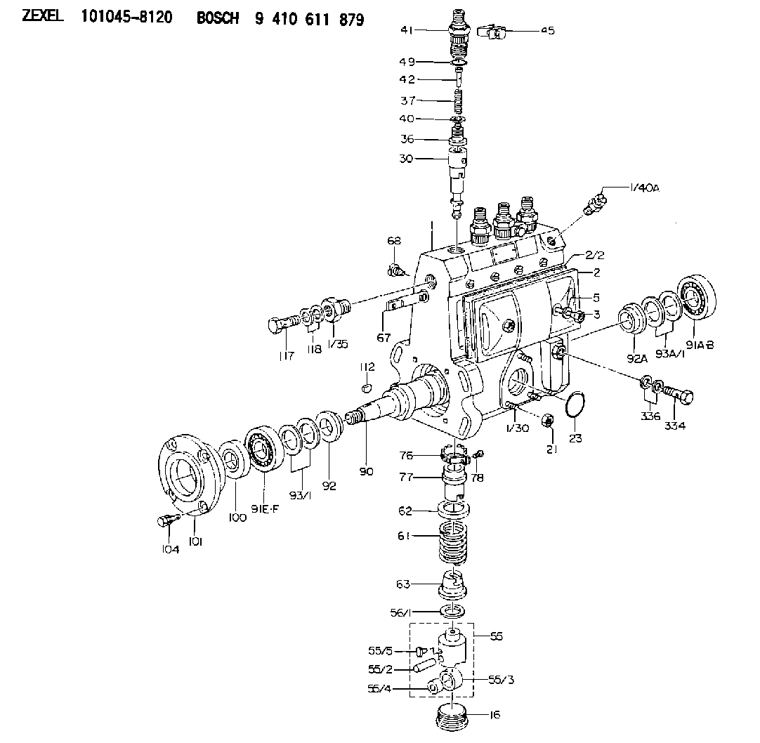
| 1. | [1] | 131063-9820 | PUMP HOUSING |
| 1/30. | [3] | 029040-6020 | STUD |
| 1/35. | [1] | 131400-0100 | ADAPTOR |
| 1/40A. | [1] | 131420-0420 | BLEEDER SCREW |
| 2. | [1] | 131028-6220 | COVER |
| 2/2. | [1] | 131011-1900 | GASKET |
| 3. | [2] | 131017-1000 | FLAT-HEAD SCREW |
| 5. | [2] | 029340-6020 | GASKET D10&6.5T1.00 |
| 16. | [4] | 131034-1401 | CAPSULE |
| 21. | [3] | 139206-0400 | UNION NUT |
| 23. | [1] | 029633-1010 | O-RING |
| 30. | [4] | 131152-4920 | PLUNGER-AND-BARREL ASSY |
| 36. | [4] | 131110-3920 | DELIVERY-VALVE ASSEMBLY |
| 37. | [4] | 131112-1600 | COILED SPRING |
| 40. | [4] | 131115-1600 | GASKET |
| 41. | [4] | 131116-7600 | FITTING |
| 42. | [4] | 131117-2300 | FILLER PIECE |
| 45. | [2] | 131122-0520 | PLATE |
| 49. | [4] | 029632-0030 | O-RING |
| 55. | [4] | 131200-2820 | TAPPET |
| 55/2. | [1] | 131203-0800 | BEARING PIN |
| 55/3. | [1] | 131204-1000 | ROLLER |
| 55/4. | [1] | 131205-0500 | BUSHING |
| 55/5. | [1] | 131206-0200 | SLIDER |
| 56/1. | [0] | 029311-0020 | SHIM D19&10T0.30 |
| 56/1. | [0] | 029311-0030 | SHIM D19&10T0.40 |
| 56/1. | [0] | 029311-0040 | SHIM D19&10T0.50 |
| 56/1. | [0] | 029311-0050 | SHIM D19&10T0.6 |
| 56/1. | [0] | 029311-0060 | SHIM D19&10T0.7 |
| 56/1. | [0] | 029311-0070 | SHIM D19&10T0.8 |
| 56/1. | [0] | 029311-0080 | SHIM D19&10T0.9 |
| 56/1. | [0] | 029311-0090 | SHIM D19&10T1 |
| 56/1. | [0] | 029311-0110 | SHIM D19&10T1.1 |
| 56/1. | [0] | 029311-0120 | SHIM D19&10T1.2 |
| 56/1. | [0] | 029311-0130 | SHIM D19&10T1.3 |
| 56/1. | [0] | 029311-0140 | SHIM D19&10T1.4 |
| 56/1. | [0] | 029311-0270 | SHIM D19&10T0.55 |
| 56/1. | [0] | 029311-0280 | SHIM D19&10T0.65 |
| 56/1. | [0] | 029311-0290 | SHIM D19&10T0.75 |
| 56/1. | [0] | 029311-0310 | SHIM D19&10T0.85 |
| 56/1. | [0] | 029311-0320 | SHIM D19&10T0.95 |
| 56/1. | [0] | 029311-0330 | SHIM D19&10T1.05 |
| 56/1. | [0] | 029311-0340 | SHIM D19&10T1.15 |
| 56/1. | [0] | 029311-0350 | SHIM D19&10T1.25 |
| 56/1. | [0] | 029311-0490 | SHIM D19&10T1.5 |
| 56/1. | [0] | 029311-0500 | SHIM D19&10T1.6 |
| 56/1. | [0] | 029311-0580 | SHIM D19&10T0.2 |
| 56/1. | [0] | 029311-0590 | SHIM D19&10T0.25 |
| 56/1. | [0] | 029311-0600 | SHIM D19&10T0.35 |
| 56/1. | [0] | 029311-0610 | SHIM D19&10T0.45 |
| 56/1. | [0] | 029311-0620 | SHIM D19&10T1.35 |
| 56/1. | [0] | 029311-0630 | SHIM D19&10T1.45 |
| 56/1. | [0] | 029311-0710 | SHIM D19&10T1.55 |
| 61. | [4] | 131215-2500 | COMPRESSION SPRING |
| 62. | [4] | 131216-0100 | SLOTTED WASHER |
| 63. | [4] | 131217-0200 | SLOTTED WASHER |
| 67. | [1] | 131254-0000 | CONTROL RACK |
| 68. | [1] | 131226-0300 | FLAT-HEAD SCREW |
| 76. | [4] | 131240-0100 | PINION |
| 77. | [4] | 131241-0100 | CONTROL SLEEVE |
| 78. | [4] | 131242-0100 | FLAT-HEAD SCREW |
| 90. | [1] | 131360-2800 | CAMSHAFT |
| 91A. | [1] | 016630-2030 | BEARING PLATE |
| 91B. | [1] | 028201-7020 | BEARING PLATE |
| 91E. | [1] | 016630-2030 | BEARING PLATE |
| 91F. | [1] | 028201-7020 | BEARING PLATE |
| 92. | [1] | 131302-0300 | SPACER RING |
| 92A. | [1] | 131302-0300 | SPACER RING |
| 93/1. | [0] | 029311-7010 | SHIM D22&17T0.1 |
| 93/1. | [0] | 029311-7020 | SHIM D22&17T0.12 |
| 93/1. | [0] | 029311-7030 | SHIM D22&17T0.14 |
| 93/1. | [0] | 029311-7040 | SHIM D22&17T0.16 |
| 93/1. | [0] | 029311-7050 | SHIM D22&17T0.18 |
| 93/1. | [0] | 029311-7060 | SHIM D22&17T0.5 |
| 93/1. | [0] | 029311-7070 | SHIM D22&17T1.0 |
| 93/1. | [0] | 029311-7090 | SHIM D22&17T0.3 |
| 93/1. | [0] | 029311-7210 | SHIM D22&17T0.7 |
| 93/1. | [0] | 029311-7220 | SHIM D22&17T1.4 |
| 93/1. | [0] | 139417-0000 | SHIM D22&17T2.4 |
| 93A/1. | [0] | 029311-7010 | SHIM D22&17T0.1 |
| 93A/1. | [0] | 029311-7020 | SHIM D22&17T0.12 |
| 93A/1. | [0] | 029311-7030 | SHIM D22&17T0.14 |
| 93A/1. | [0] | 029311-7040 | SHIM D22&17T0.16 |
| 93A/1. | [0] | 029311-7050 | SHIM D22&17T0.18 |
| 93A/1. | [0] | 029311-7060 | SHIM D22&17T0.5 |
| 93A/1. | [0] | 029311-7070 | SHIM D22&17T1.0 |
| 93A/1. | [0] | 029311-7090 | SHIM D22&17T0.3 |
| 93A/1. | [0] | 029311-7210 | SHIM D22&17T0.7 |
| 93A/1. | [0] | 029311-7220 | SHIM D22&17T1.4 |
| 93A/1. | [0] | 139417-0000 | SHIM D22&17T2.4 |
| 100. | [1] | 029621-7050 | PACKING RING |
| 101. | [1] | 131330-6200 | COVER |
| 104. | [4] | 020006-1440 | BLEEDER SCREW M6P1L14 |
| 112. | [1] | 025803-1640 | WOODRUFF KEY |
| 117. | [1] | 131401-0020 | EYE BOLT |
| 118. | [2] | 029341-4130 | GASKET D20&13.8T2* |
| 334. | [1] | 029731-0120 | EYE BOLT |
| 336. | [2] | 029341-0110 | GASKET |
Cross reference number
Zexel num
Bosch num
Firm num
Name
Information:
start by:a) remove pistons1. Check to be sure that all coolant has been removed from the cylinder block.2. Put a cover over the crankshaft journals before liners are removed. 3. Install tool (A) and remove the cylinder liners. 4. Remove filler band (1) and O-ring seals (2) from the cylinder liners.Install Cylinder Liners
1. Clean the cylinder liners and cylinder block. 2. Install the liners (1) in the cylinder block without the O-ring seals and filler bands. See CYLINDER LINER PROJECTION in TESTING AND ADJUSTING. 3. Install tooling (A) and two 5/8" - 11 NC bolts 5 1/2 in. long. Tighten the bolts evenly to 50 lb.ft. (70 N m).4. Check the liner projection with tool (B) at four locations around the liner.5. Liner projection must be .0020 to .0056 in. (0.051 to 0.142 mm). Measurements on the same liner must not be different by more than .002 in. (0.05 mm). Average measurement between liners next to each other must not be different by more than .002 in. (0.05 mm). The maximum permissible difference between average projection of all cylinder liners under one cylinder head is .004 in. (0.10 mm). The liner projection can change if the liner is turned in the bore. 6. If the liner projection is not .0020 to .0056 in. (0.051 to 0.142 mm), check the thickness of the liner flange (2) and the depth of the liner bore in the cylinder block. The thickness of the liner flange (2) must be .4048 .0008 in. (10.282 0.020 mm).7. The depth of the liner bore in the cylinder block must be .401 .001 in. (10.19 0.03 mm). If the liner bore in the block is worn and the measurement is not correct, the liner bore can be corrected with a cylinder block counterboring tool. See SPECIAL INSTRUCTIONS, FORM FM055228.8. Put a mark on the liner and cylinder block so the liner can be installed in the same position from which it was removed. 9. Install new O-ring seals (4) on the cylinder liners. Put liquid soap on the O-ring seals and in the bases in the cylinder block.
The liners must be installed in the cylinder block immediately after filler band (3) is installed. Make sure the marks on the liners and the cylinder block are in alignment when the cylinder liners are installed.
10. Put (dip) the filler band completely in clean SAE 30 oil and install it on the liner immediately.11. Install the liner in the cylinder block immediately with tooling (C).end by:a) install pistons