Information fuel-injection pump
BOSCH
9 410 614 387
9410614387
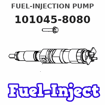
ZEXEL
101045-8080
1010458080
ISUZU
8944593950
8944593950
Rating:
Scheme ###:
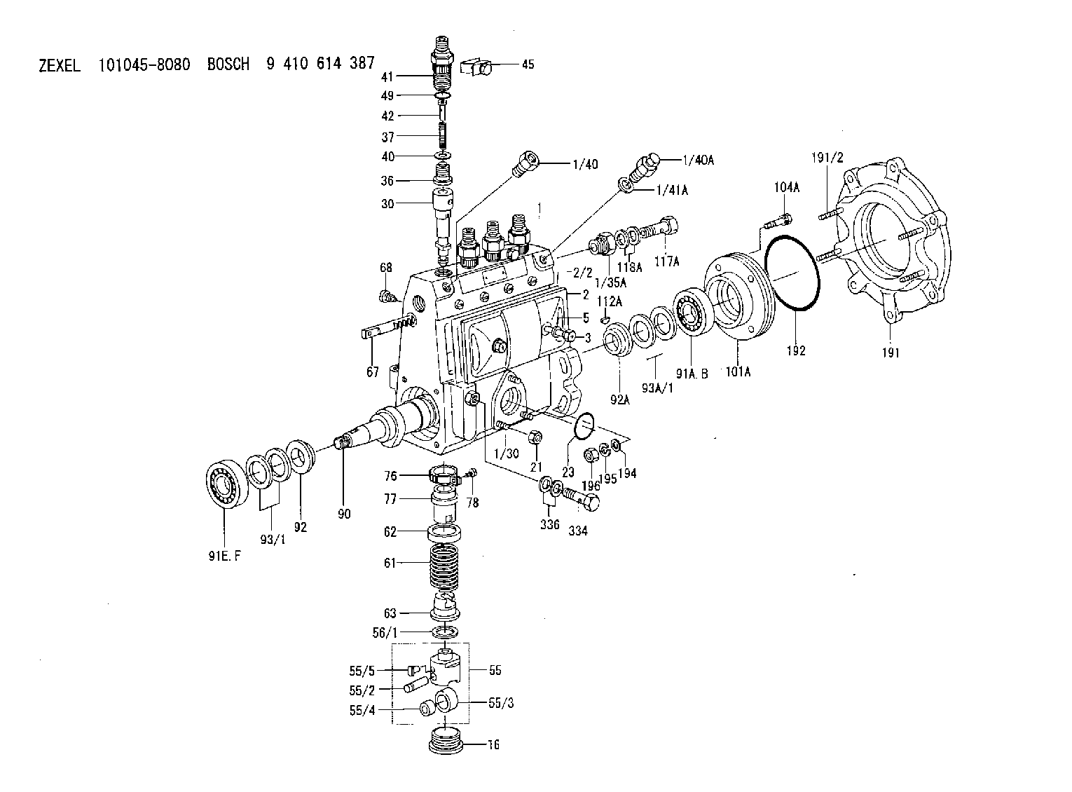
| 1. | [1] | 131062-7420 | PUMP HOUSING |
| 1/30. | [3] | 029040-6020 | STUD |
| 1/35A. | [1] | 131400-0100 | ADAPTOR |
| 1/40. | [1] | 131423-0800 | ADAPTOR |
| 1/40A. | [1] | 131420-0420 | BLEEDER SCREW |
| 1/41A. | [1] | 026512-1540 | GASKET D15.4&12.2T1.50 |
| 2. | [1] | 131028-6220 | COVER |
| 2/2. | [1] | 131011-1900 | GASKET |
| 3. | [2] | 131017-1000 | FLAT-HEAD SCREW |
| 5. | [2] | 029340-6020 | GASKET D10&6.5T1.00 |
| 16. | [4] | 131034-1401 | CAPSULE |
| 21. | [3] | 139206-0400 | UNION NUT |
| 23. | [1] | 029633-1010 | O-RING |
| 30. | [4] | 131152-9020 | PLUNGER-AND-BARREL ASSY |
| 36. | [4] | 131110-4720 | DELIVERY-VALVE ASSEMBLY |
| 37. | [4] | 131112-2300 | COILED SPRING |
| 40. | [4] | 131115-1600 | GASKET |
| 41. | [4] | 131116-7600 | FITTING |
| 42. | [4] | 131117-2300 | FILLER PIECE |
| 45. | [2] | 131122-0520 | PLATE |
| 49. | [4] | 029632-0030 | O-RING |
| 55. | [4] | 131200-0220 | TAPPET |
| 55/2. | [1] | 131203-0200 | BEARING PIN |
| 55/3. | [1] | 131204-1000 | ROLLER |
| 55/4. | [1] | 131205-0500 | BUSHING |
| 55/5. | [1] | 131206-0200 | SLIDER |
| 56/1. | [0] | 029311-0020 | SHIM D19&10T0.30 |
| 56/1. | [0] | 029311-0030 | SHIM D19&10T0.40 |
| 56/1. | [0] | 029311-0040 | SHIM D19&10T0.50 |
| 56/1. | [0] | 029311-0050 | SHIM D19&10T0.6 |
| 56/1. | [0] | 029311-0060 | SHIM D19&10T0.7 |
| 56/1. | [0] | 029311-0070 | SHIM D19&10T0.8 |
| 56/1. | [0] | 029311-0080 | SHIM D19&10T0.9 |
| 56/1. | [0] | 029311-0090 | SHIM D19&10T1 |
| 56/1. | [0] | 029311-0110 | SHIM D19&10T1.1 |
| 56/1. | [0] | 029311-0120 | SHIM D19&10T1.2 |
| 56/1. | [0] | 029311-0130 | SHIM D19&10T1.3 |
| 56/1. | [0] | 029311-0140 | SHIM D19&10T1.4 |
| 56/1. | [0] | 029311-0270 | SHIM D19&10T0.55 |
| 56/1. | [0] | 029311-0280 | SHIM D19&10T0.65 |
| 56/1. | [0] | 029311-0290 | SHIM D19&10T0.75 |
| 56/1. | [0] | 029311-0310 | SHIM D19&10T0.85 |
| 56/1. | [0] | 029311-0320 | SHIM D19&10T0.95 |
| 56/1. | [0] | 029311-0330 | SHIM D19&10T1.05 |
| 56/1. | [0] | 029311-0340 | SHIM D19&10T1.15 |
| 56/1. | [0] | 029311-0350 | SHIM D19&10T1.25 |
| 56/1. | [0] | 029311-0490 | SHIM D19&10T1.5 |
| 56/1. | [0] | 029311-0500 | SHIM D19&10T1.6 |
| 56/1. | [0] | 029311-0580 | SHIM D19&10T0.2 |
| 56/1. | [0] | 029311-0590 | SHIM D19&10T0.25 |
| 56/1. | [0] | 029311-0600 | SHIM D19&10T0.35 |
| 56/1. | [0] | 029311-0610 | SHIM D19&10T0.45 |
| 56/1. | [0] | 029311-0620 | SHIM D19&10T1.35 |
| 56/1. | [0] | 029311-0630 | SHIM D19&10T1.45 |
| 56/1. | [0] | 029311-0710 | SHIM D19&10T1.55 |
| 61. | [4] | 131215-2500 | COMPRESSION SPRING |
| 62. | [4] | 131216-0100 | SLOTTED WASHER |
| 63. | [4] | 131217-0200 | SLOTTED WASHER |
| 67. | [1] | 131254-0000 | CONTROL RACK |
| 68. | [1] | 131226-0300 | FLAT-HEAD SCREW |
| 76. | [4] | 131240-0100 | PINION |
| 77. | [4] | 131241-0100 | CONTROL SLEEVE |
| 78. | [4] | 131242-0100 | FLAT-HEAD SCREW |
| 90. | [1] | 131360-1300 | CAMSHAFT |
| 91A. | [1] | 016630-2030 | BEARING PLATE |
| 91B. | [1] | 028201-7020 | BEARING PLATE |
| 91E. | [1] | 016630-2030 | BEARING PLATE |
| 91F. | [1] | 028201-7020 | BEARING PLATE |
| 92. | [1] | 131302-0300 | SPACER RING |
| 92A. | [1] | 131302-0300 | SPACER RING |
| 93/1. | [0] | 029311-7010 | SHIM D22&17T0.1 |
| 93/1. | [0] | 029311-7020 | SHIM D22&17T0.12 |
| 93/1. | [0] | 029311-7030 | SHIM D22&17T0.14 |
| 93/1. | [0] | 029311-7040 | SHIM D22&17T0.16 |
| 93/1. | [0] | 029311-7050 | SHIM D22&17T0.18 |
| 93/1. | [0] | 029311-7060 | SHIM D22&17T0.5 |
| 93/1. | [0] | 029311-7070 | SHIM D22&17T1.0 |
| 93/1. | [0] | 029311-7090 | SHIM D22&17T0.3 |
| 93/1. | [0] | 029311-7210 | SHIM D22&17T0.7 |
| 93/1. | [0] | 029311-7220 | SHIM D22&17T1.4 |
| 93/1. | [0] | 139417-0000 | SHIM D22&17T2.4 |
| 93A/1. | [0] | 029311-7010 | SHIM D22&17T0.1 |
| 93A/1. | [0] | 029311-7020 | SHIM D22&17T0.12 |
| 93A/1. | [0] | 029311-7030 | SHIM D22&17T0.14 |
| 93A/1. | [0] | 029311-7040 | SHIM D22&17T0.16 |
| 93A/1. | [0] | 029311-7050 | SHIM D22&17T0.18 |
| 93A/1. | [0] | 029311-7060 | SHIM D22&17T0.5 |
| 93A/1. | [0] | 029311-7070 | SHIM D22&17T1.0 |
| 93A/1. | [0] | 029311-7090 | SHIM D22&17T0.3 |
| 93A/1. | [0] | 029311-7210 | SHIM D22&17T0.7 |
| 93A/1. | [0] | 029311-7220 | SHIM D22&17T1.4 |
| 93A/1. | [0] | 139417-0000 | SHIM D22&17T2.4 |
| 101A. | [1] | 131330-5900 | COVER |
| 104A. | [4] | 020006-1440 | BLEEDER SCREW M6P1L14 |
| 112A. | [1] | 025803-1640 | WOODRUFF KEY |
| 117A. | [1] | 029731-4580 | EYE BOLT |
| 118A. | [2] | 029341-4080 | GASKET |
| 191. | [1] | 131459-9720 | BRACKET |
| 191/2. | [4] | 029041-0010 | STUD |
| 192. | [1] | 139768-0000 | O-RING |
| 194. | [4] | 014011-0140 | PLAIN WASHER D22&10.5T1.6 |
| 195. | [4] | 014111-0440 | LOCKING WASHER |
| 196. | [4] | 131465-0000 | UNION NUT |
| 334. | [1] | 029731-0410 | EYE BOLT |
| 336. | [2] | 029341-0090 | GASKET |
Cross reference number
Zexel num
Bosch num
Firm num
Name
Information:
start by:a) remove turbocharger 1. Put the turbocharger in position on tool (A). Move tool (A) so the compressor housing is up. 2. For installation alignment purposes, make a mark on the center housing and turbine housing. Bend down the lock plates and remove six bolts (1). If some of the bolts are hard to remove, put penetrating oil on the bolt and hit the flat of the bolt head with a punch and hammer. 3. Lift the center housing and turbine wheel out of the turbine housing. If the assembly is hard to get apart, lift up on the compressor housing and hit the turbine housing with a soft hammer. 4. Remove clamp (2) from the compressor housing. For installation alignment purposes, make a mark on the center housing and the compressor housing. 5. Lift the center housing out of the compressor housing. Put the turbine wheel in tooling (B).6. Remove nut (3) with a universal socket. Remove O-ring (4).
Do not put a side force on the shaft when the nut is removed.
7. Heat the compressor wheel in oil for no more than ten minutes. The temperature of the oil must be 350° 25°F (176° 14°C).
The bearing heating oil used to heat the compressor wheel must have a flash point above 400°F (204°C).
8. Immediately after removing the compressor wheel from the oil, put the center housing in a press and use tooling (C) and (D) to remove the compressor wheel and center housing from the shaft.
Do not let the turbine wheel hit the bottom of the press.
9. Put the turbine wheel in tooling (B) and remove ring (6) and shroud (5). 10. Remove three bolts (7) and the three lock plates from center housing (8). 11. Remove plate (9) with tool (E). Remove the O-ring from plate (9). 12. Remove spacer (10) from plate (9). Remove collar (11) and thrust bearing (15). Remove bearing (12) and put a long dye mark on the top face of the bearing. Use tool (F) to remove rings (16) and (13). Remove bearing (17) and put a short dye mark on the top face of the bearing. Remove ring (14) with tool (F). The dye marks are for identification when installing the bearings.13. Inspect all parts and install new parts if needed. Use Special Instruction Form No. GMG00153-01, Turbocharger Reconditioning, Form No. FEG45138, Analyzing Turbocharger Failure and Video Tape JEG08054 (1/2 inch reel) (JEG09052-cassette), Turbocharger Reconditioning I (AIRESEARCH) for references.Assemble Turbocharger
1. Make sure all oil passages are open and clean. Put clean engine oil on all parts before assembly. 2. Install ring (3) with tool (A). Install bearing (4) with the short dye mark up. Install rings (2) and (1) with tool (A). Rings (1), (2) and (3) must be installed with the round edge toward the bearing. 3. Install shroud (5) on the turbine shaft. Install ring (6). Put 6V2055 High Vacuum Grease on ring (6) and fill the groove for the ring to one half depth all