Information fuel-injection pump
BOSCH
9 410 612 632
9410612632
ZEXEL
101043-8620
1010438620
NISSAN-DIESEL
1670390065
1670390065
Rating:
Scheme ###:
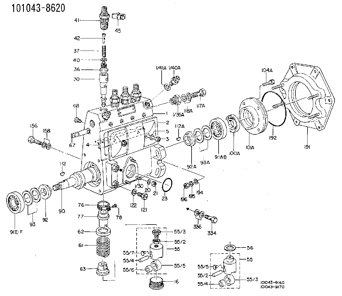
| 1. | [1] | 131062-5020 | PUMP HOUSING |
| 1/30. | [3] | 029040-6020 | STUD |
| 1/35A. | [1] | 131400-0100 | ADAPTOR |
| 1/40. | [1] | 131420-0420 | BLEEDER SCREW |
| 1/40A. | [1] | 131420-0420 | BLEEDER SCREW |
| 1/41. | [1] | 026512-1540 | GASKET D15.4&12.2T1.50 |
| 1/41A. | [1] | 026512-1540 | GASKET D15.4&12.2T1.50 |
| 2. | [1] | 131028-6220 | COVER |
| 2/2. | [1] | 131011-1900 | GASKET |
| 3. | [2] | 131017-1000 | FLAT-HEAD SCREW |
| 5. | [2] | 029340-6020 | GASKET D10&6.5T1.00 |
| 16. | [4] | 131034-1401 | CAPSULE |
| 21. | [3] | 139206-0400 | UNION NUT |
| 23. | [1] | 029633-1010 | O-RING |
| 30. | [4] | 131101-7020 | PLUNGER-AND-BARREL ASSY |
| 36. | [4] | 131110-0320 | DELIVERY-VALVE ASSEMBLY |
| 37. | [4] | 131112-0600 | COILED SPRING |
| 40. | [4] | 131115-0200 | GASKET |
| 41. | [4] | 131116-0500 | FITTING |
| 45. | [2] | 131122-0520 | PLATE |
| 55. | [4] | 131200-0620 | TAPPET |
| 55. | [4] | 131200-0620 | TAPPET |
| 55/2. | [1] | 131201-0100 | UNION NUT |
| 55/2. | [1] | 131201-0100 | UNION NUT |
| 55/3. | [1] | 131202-0100 | HEXAGON SCREW |
| 55/3. | [1] | 131202-0100 | HEXAGON SCREW |
| 55/4. | [1] | 131203-0200 | BEARING PIN |
| 55/4. | [1] | 131203-0200 | BEARING PIN |
| 55/5. | [1] | 131204-1000 | ROLLER |
| 55/5. | [1] | 131204-1000 | ROLLER |
| 55/6. | [1] | 131205-0500 | BUSHING |
| 55/7. | [1] | 131206-0200 | SLIDER |
| 61. | [4] | 131215-2400 | COMPRESSION SPRING |
| 62. | [4] | 131216-0100 | SLOTTED WASHER |
| 63. | [4] | 131217-0100 | SLOTTED WASHER |
| 67. | [1] | 131254-0000 | CONTROL RACK |
| 68. | [1] | 131226-0300 | FLAT-HEAD SCREW |
| 76. | [4] | 131240-0100 | PINION |
| 77. | [4] | 131241-0100 | CONTROL SLEEVE |
| 78. | [4] | 131242-0100 | FLAT-HEAD SCREW |
| 90. | [1] | 131360-0500 | CAMSHAFT |
| 91A. | [1] | 016630-2030 | BEARING PLATE |
| 91B. | [1] | 028201-7020 | BEARING PLATE |
| 91E. | [1] | 016630-2030 | BEARING PLATE |
| 91F. | [1] | 028201-7020 | BEARING PLATE |
| 92. | [1] | 131302-0300 | SPACER RING |
| 92A. | [1] | 131302-0300 | SPACER RING |
| 93/1. | [0] | 029311-7010 | SHIM D22&17T0.1 |
| 93/1. | [0] | 029311-7020 | SHIM D22&17T0.12 |
| 93/1. | [0] | 029311-7030 | SHIM D22&17T0.14 |
| 93/1. | [0] | 029311-7040 | SHIM D22&17T0.16 |
| 93/1. | [0] | 029311-7050 | SHIM D22&17T0.18 |
| 93/1. | [0] | 029311-7060 | SHIM D22&17T0.5 |
| 93/1. | [0] | 029311-7070 | SHIM D22&17T1.0 |
| 93/1. | [0] | 029311-7090 | SHIM D22&17T0.3 |
| 93/1. | [0] | 029311-7210 | SHIM D22&17T0.7 |
| 93/1. | [0] | 029311-7220 | SHIM D22&17T1.4 |
| 93/1. | [0] | 139417-0000 | SHIM D22&17T2.4 |
| 93A/1. | [0] | 029311-7010 | SHIM D22&17T0.1 |
| 93A/1. | [0] | 029311-7020 | SHIM D22&17T0.12 |
| 93A/1. | [0] | 029311-7030 | SHIM D22&17T0.14 |
| 93A/1. | [0] | 029311-7040 | SHIM D22&17T0.16 |
| 93A/1. | [0] | 029311-7050 | SHIM D22&17T0.18 |
| 93A/1. | [0] | 029311-7060 | SHIM D22&17T0.5 |
| 93A/1. | [0] | 029311-7070 | SHIM D22&17T1.0 |
| 93A/1. | [0] | 029311-7090 | SHIM D22&17T0.3 |
| 93A/1. | [0] | 029311-7210 | SHIM D22&17T0.7 |
| 93A/1. | [0] | 029311-7220 | SHIM D22&17T1.4 |
| 93A/1. | [0] | 139417-0000 | SHIM D22&17T2.4 |
| 101A. | [1] | 131330-2200 | COVER |
| 104A. | [4] | 020006-1440 | BLEEDER SCREW M6P1L14 |
| 112A. | [1] | 025803-1640 | WOODRUFF KEY |
| 117A. | [1] | 029731-4080 | EYE BOLT |
| 121. | [1] | 029111-0010 | CAPSULE |
| 122. | [1] | 029341-0020 | GASKET |
| 334. | [1] | 029731-0120 | EYE BOLT |
| 336. | [2] | 026510-1340 | GASKET D13.4&10.2T1 |
Cross reference number
Zexel num
Bosch num
Firm num
Name
101043-8620
1670390065 NISSAN-DIESEL
FUEL-INJECTION PUMP
* Q
* Q
Information:
1. Remove the bolts and exhaust support (1) and the extension as a unit. 2. Remove extension (3) from the support.3. Remove two seal rings (2) from the extension. 4. Remove two bolts (5) from the clips.5. Remove the bolts and disconnect oil line (4) from the turbocharger. Remove the gasket. 6. Remove bolts (6) and disconnect the drain line from the turbocharger.7. Remove the gasket. 8. Remove bolts (7) that hold the manifold to the aftercooler. 9. Install tool (A) on the turbocharger and fasten a hoist.10. Remove bolts (9) that hold the turbocharger to the support bracket. Remove turbocharger (8) and the gasket. The weight of the turbocharger is 55 lb. (25 kg).11. Remove pipe (10) and the manifold from the turbocharger as a unit.Install Turbocharger
1. Install pipe (3) and the manifold as a unit on the turbocharger.2. Install tool (A) and fasten a hoist.3. Put turbocharger (1) in position and install gasket (2).4. Put 5P3931 Anti-Seize Compound on the bolts that hold the turbocharger in position. Install the bolts and tigthen them to a torque of 40 4 lb.ft. (54 5 N m). 5. Put gasket (4) in position and install the bolts. 6. Put gasket (5) and tube (6) in position and install the bolts. Put 5P3931 Anti-Seize Compound on the bolts. 7. Put gasket (7) and tube (8) in position. Put 5P3931 Anti-Seize Compound on the bolts and install them. 8. Put clips (9) and the bolts in position. 9. Put seal rings (10) in position on extension (11). Install the extension in the support. 10. Put support (12) and the extension in position. Put 5P3931 Anti-Seize Compound on the bolts. Install the bolts and tighten them to a torque of 40 4 lb.ft. (54 5 N m).
1. Install pipe (3) and the manifold as a unit on the turbocharger.2. Install tool (A) and fasten a hoist.3. Put turbocharger (1) in position and install gasket (2).4. Put 5P3931 Anti-Seize Compound on the bolts that hold the turbocharger in position. Install the bolts and tigthen them to a torque of 40 4 lb.ft. (54 5 N m). 5. Put gasket (4) in position and install the bolts. 6. Put gasket (5) and tube (6) in position and install the bolts. Put 5P3931 Anti-Seize Compound on the bolts. 7. Put gasket (7) and tube (8) in position. Put 5P3931 Anti-Seize Compound on the bolts and install them. 8. Put clips (9) and the bolts in position. 9. Put seal rings (10) in position on extension (11). Install the extension in the support. 10. Put support (12) and the extension in position. Put 5P3931 Anti-Seize Compound on the bolts. Install the bolts and tighten them to a torque of 40 4 lb.ft. (54 5 N m).