Information fuel-injection pump
BOSCH
9 410 610 739
9410610739
ZEXEL
101041-8660
1010418660
ISUZU
8971698210
8971698210

Rating:
Scheme ###:
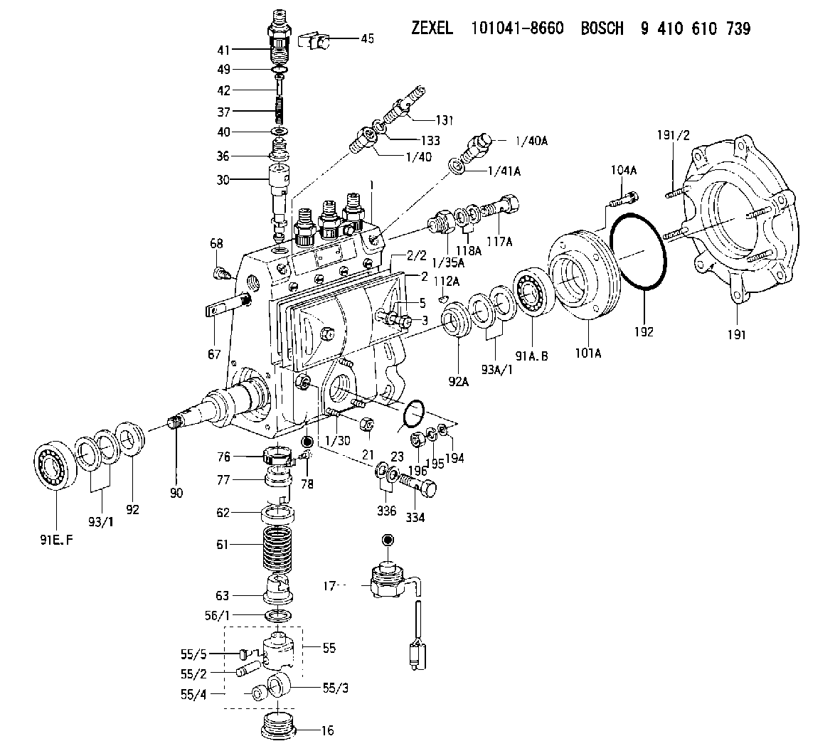
| 1. | [1] | 131062-6920 | PUMP HOUSING |
| 1/30. | [3] | 029040-6020 | STUD |
| 1/35A. | [1] | 131400-0100 | ADAPTOR |
| 1/40. | [1] | 131423-0800 | ADAPTOR |
| 1/40A. | [1] | 131420-0420 | BLEEDER SCREW |
| 1/41A. | [1] | 026512-1540 | GASKET D15.4&12.2T1.50 |
| 2. | [1] | 131028-6220 | COVER |
| 2/2. | [1] | 131011-1900 | GASKET |
| 3. | [2] | 131017-1000 | FLAT-HEAD SCREW |
| 5. | [2] | 029340-6020 | GASKET D10&6.5T1.00 |
| 16. | [3] | 131034-1401 | CAPSULE |
| 17. | [1] | 131034-3100 | PULSE GENERATOR |
| 21. | [3] | 139206-0400 | UNION NUT |
| 23. | [1] | 029633-1010 | O-RING |
| 30. | [4] | 131152-8720 | PLUNGER-AND-BARREL ASSY |
| 36. | [4] | 131160-7520 | DELIVERY-VALVE ASSEMBLY |
| 37. | [4] | 131112-2300 | COILED SPRING |
| 40. | [4] | 131115-1600 | GASKET |
| 41. | [4] | 131116-7600 | FITTING |
| 42. | [4] | 131117-2300 | FILLER PIECE |
| 45. | [2] | 131122-0520 | PLATE |
| 49. | [4] | 029632-0030 | O-RING |
| 55. | [4] | 131200-0220 | TAPPET |
| 55/2. | [1] | 131203-0200 | BEARING PIN |
| 55/3. | [1] | 131204-1000 | ROLLER |
| 55/4. | [1] | 131205-0500 | BUSHING |
| 55/5. | [1] | 131206-0200 | SLIDER |
| 56/1. | [0] | 029311-0020 | SHIM D19&10T0.30 |
| 56/1. | [0] | 029311-0030 | SHIM D19&10T0.40 |
| 56/1. | [0] | 029311-0040 | SHIM D19&10T0.50 |
| 56/1. | [0] | 029311-0050 | SHIM D19&10T0.6 |
| 56/1. | [0] | 029311-0060 | SHIM D19&10T0.7 |
| 56/1. | [0] | 029311-0070 | SHIM D19&10T0.8 |
| 56/1. | [0] | 029311-0080 | SHIM D19&10T0.9 |
| 56/1. | [0] | 029311-0090 | SHIM D19&10T1 |
| 56/1. | [0] | 029311-0110 | SHIM D19&10T1.1 |
| 56/1. | [0] | 029311-0120 | SHIM D19&10T1.2 |
| 56/1. | [0] | 029311-0130 | SHIM D19&10T1.3 |
| 56/1. | [0] | 029311-0140 | SHIM D19&10T1.4 |
| 56/1. | [0] | 029311-0270 | SHIM D19&10T0.55 |
| 56/1. | [0] | 029311-0280 | SHIM D19&10T0.65 |
| 56/1. | [0] | 029311-0290 | SHIM D19&10T0.75 |
| 56/1. | [0] | 029311-0310 | SHIM D19&10T0.85 |
| 56/1. | [0] | 029311-0320 | SHIM D19&10T0.95 |
| 56/1. | [0] | 029311-0330 | SHIM D19&10T1.05 |
| 56/1. | [0] | 029311-0340 | SHIM D19&10T1.15 |
| 56/1. | [0] | 029311-0350 | SHIM D19&10T1.25 |
| 56/1. | [0] | 029311-0490 | SHIM D19&10T1.5 |
| 56/1. | [0] | 029311-0500 | SHIM D19&10T1.6 |
| 56/1. | [0] | 029311-0580 | SHIM D19&10T0.2 |
| 56/1. | [0] | 029311-0590 | SHIM D19&10T0.25 |
| 56/1. | [0] | 029311-0600 | SHIM D19&10T0.35 |
| 56/1. | [0] | 029311-0610 | SHIM D19&10T0.45 |
| 56/1. | [0] | 029311-0620 | SHIM D19&10T1.35 |
| 56/1. | [0] | 029311-0630 | SHIM D19&10T1.45 |
| 56/1. | [0] | 029311-0710 | SHIM D19&10T1.55 |
| 61. | [4] | 131215-2500 | COMPRESSION SPRING |
| 62. | [4] | 131216-0100 | SLOTTED WASHER |
| 63. | [4] | 131217-0200 | SLOTTED WASHER |
| 67. | [1] | 131254-0000 | CONTROL RACK |
| 68. | [1] | 131226-0300 | FLAT-HEAD SCREW |
| 76. | [4] | 131240-0100 | PINION |
| 77. | [4] | 131241-0100 | CONTROL SLEEVE |
| 78. | [4] | 131242-0100 | FLAT-HEAD SCREW |
| 90. | [1] | 131360-1900 | CAMSHAFT |
| 91A. | [1] | 016630-2030 | BEARING PLATE |
| 91B. | [1] | 028201-7020 | BEARING PLATE |
| 91E. | [1] | 016630-2030 | BEARING PLATE |
| 91F. | [1] | 028201-7020 | BEARING PLATE |
| 92. | [1] | 131302-0300 | SPACER RING |
| 92A. | [1] | 131302-0300 | SPACER RING |
| 93/1. | [0] | 029311-7010 | SHIM D22&17T0.1 |
| 93/1. | [0] | 029311-7020 | SHIM D22&17T0.12 |
| 93/1. | [0] | 029311-7030 | SHIM D22&17T0.14 |
| 93/1. | [0] | 029311-7040 | SHIM D22&17T0.16 |
| 93/1. | [0] | 029311-7050 | SHIM D22&17T0.18 |
| 93/1. | [0] | 029311-7060 | SHIM D22&17T0.5 |
| 93/1. | [0] | 029311-7070 | SHIM D22&17T1.0 |
| 93/1. | [0] | 029311-7090 | SHIM D22&17T0.3 |
| 93/1. | [0] | 029311-7210 | SHIM D22&17T0.7 |
| 93/1. | [0] | 029311-7220 | SHIM D22&17T1.4 |
| 93/1. | [0] | 139417-0000 | SHIM D22&17T2.4 |
| 93A/1. | [0] | 029311-7010 | SHIM D22&17T0.1 |
| 93A/1. | [0] | 029311-7020 | SHIM D22&17T0.12 |
| 93A/1. | [0] | 029311-7030 | SHIM D22&17T0.14 |
| 93A/1. | [0] | 029311-7040 | SHIM D22&17T0.16 |
| 93A/1. | [0] | 029311-7050 | SHIM D22&17T0.18 |
| 93A/1. | [0] | 029311-7060 | SHIM D22&17T0.5 |
| 93A/1. | [0] | 029311-7070 | SHIM D22&17T1.0 |
| 93A/1. | [0] | 029311-7090 | SHIM D22&17T0.3 |
| 93A/1. | [0] | 029311-7210 | SHIM D22&17T0.7 |
| 93A/1. | [0] | 029311-7220 | SHIM D22&17T1.4 |
| 93A/1. | [0] | 139417-0000 | SHIM D22&17T2.4 |
| 101A. | [1] | 131330-5900 | COVER |
| 104A. | [4] | 020006-1440 | BLEEDER SCREW M6P1L14 |
| 112A. | [1] | 025803-1610 | WOODRUFF KEY |
| 117A. | [1] | 029731-4580 | EYE BOLT |
| 118A. | [2] | 029341-4080 | GASKET |
| 131. | [1] | 131424-7820 | CONNECTOR |
| 133. | [1] | 029341-4080 | GASKET |
| 191. | [1] | 131459-7820 | BRACKET |
| 191/2. | [4] | 029041-0010 | STUD |
| 192. | [1] | 139768-0000 | O-RING |
| 194. | [4] | 014011-0140 | PLAIN WASHER D22&10.5T1.6 |
| 195. | [4] | 014111-0440 | LOCKING WASHER |
| 196. | [4] | 131465-0000 | UNION NUT |
| 334. | [1] | 029731-0410 | EYE BOLT |
| 336. | [2] | 029341-0090 | GASKET |
Cross reference number
Zexel num
Bosch num
Firm num
Name
101041-8660
8971698210 ISUZU
FUEL-INJECTION PUMP
Q 14BC FUEL INJECTION PUMP PE4A,5A, PE
Q 14BC FUEL INJECTION PUMP PE4A,5A, PE
Information:
start by: a) separation of governor from fuel injection pump housing1. Remove the cover (16) from rack centering pin. Move the rack to the fuel "OFF" position, and push in on the centering pin (15). Install the cover (16) as shown to keep the centering pin in position during disassembly and assembly of injection pump housing. 2. Move the rack toward the fuel "ON" position until the slot in rack (13) is against the rack centering pin (15). The rack is now in the "CENTER" position.
Do not try to remove the fuel injection pumps if the rack is not in "CENTER" position.
3. Remove the fuel injection pumps as follows: a) Remove the caps and felt washer (1).b) Install wrench (A), and remove the bushing (2) from housing. c) Install extractor (B).d) Remove the bushing (2) and wrench (A).e) Remove the seal (3).f) Lift the fuel injection pump up and out of housing.g) Remove the spacer (9). Keep the spacer (9) together with its respective fuel injection pump. Put identification on the pumps and spacers as to their location in the pump housing.4. Disassemble the fuel injection pumps as follows: a) Remove the ring (7), bonnet (4), check valve (6), and spring (5) from barrel (8).b) Remove the plunger assembly (11), washer (12), and spring (10) from barrel (8).
Be very careful when disassembling and assembling the fuel injection pumps to prevent damage to the plunger surfaces. The barrel and plunger assemblies are fitted together, and must not be used with other barrels or plunger assemblies.
5. Remove the rack centering pin, spring, and cover. 6. Remove the rack (13), and lifters (14). Put identification on the lifters as to their location in the pump housing. Keep the lifters with their respective pumps and spacers. 7. Remove the bolt, lock, and plate (17) from the camshaft. Remove the spring and gear assembly (18).8. Remove the camshaft (20) from pump housing.9. Remove the rack bearings (19) from housing. 10. Use tool setup (C) to remove the camshaft bearings from the fuel injection pump housing.Assemble Fuel Injection Pump Housing
1. Use tool group (D) to install the rack bearing in the accessory drive housing end of injection pump housing.2. Install the rack bearing in governor end of housing using tool setup (E). The bearing must be installed .195 .005 in. (4.95 0.13 mm) below outside face of pump housing.3. Use tool group (C) to install the camshaft bearings in housing. Make sure the oil holes in bearings are in alignment with oil holes in pump housing. 4. Put clean engine oil on the camshaft bearings. Install the camshaft (1) in pump housing. 5. Install the gear (3), spring, plate, lock, and bolt (2) on the camshaft.6. Put clean engine oil on lobes of camshaft. 7. Install the lifters (4) in their respective positions in pump housing. Install the spacers in their correct locations in housing. If new lifters are to be installed, it will be necessary to check the timing