Information fuel-injection pump
BOSCH
9 410 610 721
9410610721
ZEXEL
101041-8440
1010418440
ISUZU
8971608060
8971608060

Rating:
Scheme ###:
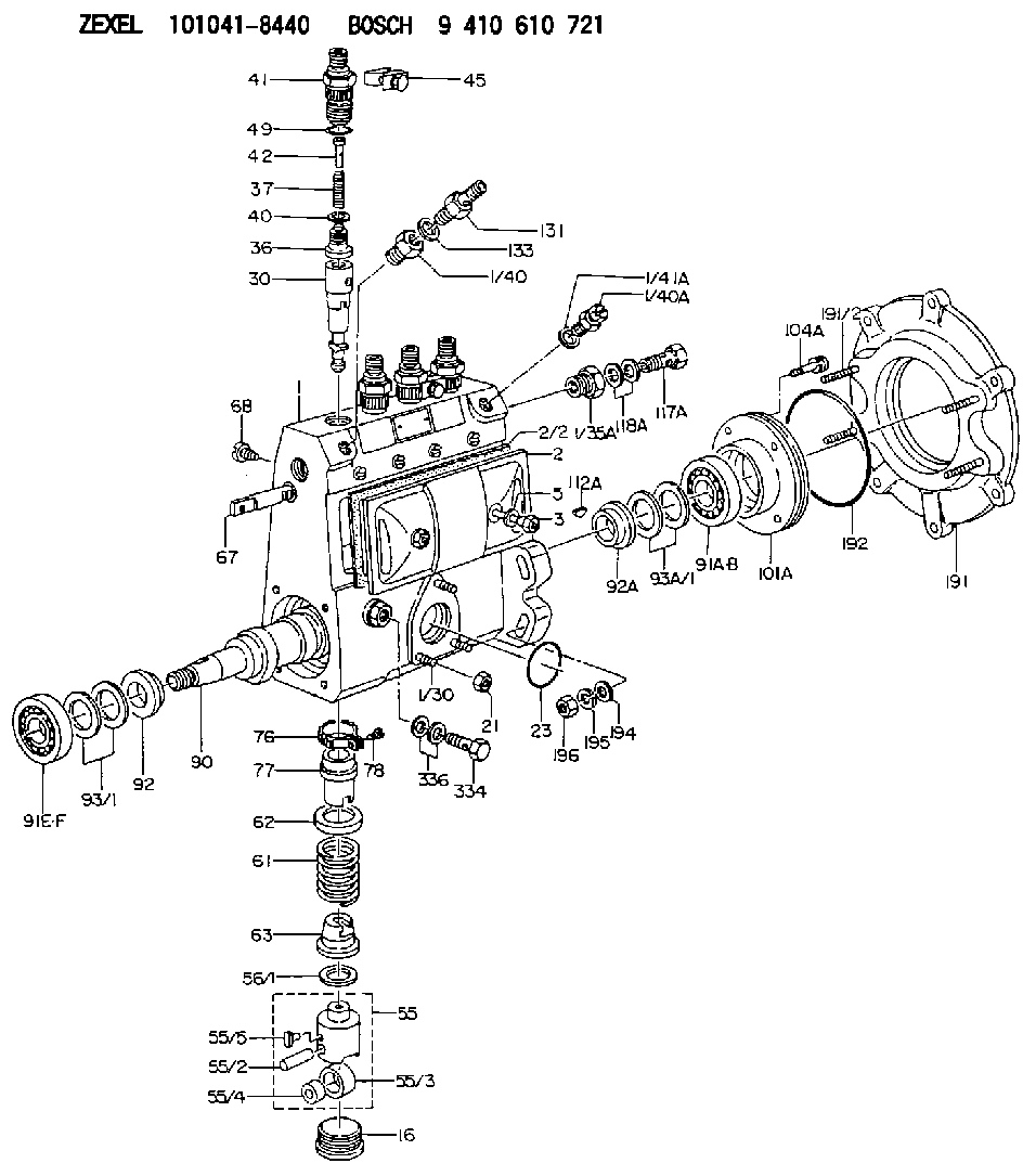
| 1. | [1] | 131062-6920 | PUMP HOUSING |
| 1/30. | [3] | 029040-6020 | STUD |
| 1/35A. | [1] | 131400-0100 | ADAPTOR |
| 1/40. | [1] | 131423-0800 | ADAPTOR |
| 1/40A. | [1] | 131420-0420 | BLEEDER SCREW |
| 1/41A. | [1] | 026512-1540 | GASKET D15.4&12.2T1.50 |
| 2. | [1] | 131028-6220 | COVER |
| 2/2. | [1] | 131011-1900 | GASKET |
| 3. | [2] | 131017-1000 | FLAT-HEAD SCREW |
| 5. | [2] | 029340-6020 | GASKET D10&6.5T1.00 |
| 16. | [4] | 131034-1401 | CAPSULE |
| 21. | [3] | 139206-0400 | UNION NUT |
| 23. | [1] | 029633-1010 | O-RING |
| 30. | [4] | 131152-9520 | PLUNGER-AND-BARREL ASSY |
| 36. | [4] | 131110-8620 | DELIVERY-VALVE ASSEMBLY |
| 37. | [4] | 131112-3500 | COMPRESSION SPRING |
| 40. | [4] | 131115-1600 | GASKET |
| 41. | [4] | 131116-7600 | FITTING |
| 42. | [4] | 131117-2300 | FILLER PIECE |
| 45. | [2] | 131122-0520 | PLATE |
| 49. | [4] | 029632-0030 | O-RING |
| 55. | [4] | 131200-0220 | TAPPET |
| 55/2. | [1] | 131203-0200 | BEARING PIN |
| 55/3. | [1] | 131204-1000 | ROLLER |
| 55/4. | [1] | 131205-0500 | BUSHING |
| 55/5. | [1] | 131206-0200 | SLIDER |
| 56/1. | [0] | 029311-0020 | SHIM D19&10T0.30 |
| 56/1. | [0] | 029311-0030 | SHIM D19&10T0.40 |
| 56/1. | [0] | 029311-0040 | SHIM D19&10T0.50 |
| 56/1. | [0] | 029311-0050 | SHIM D19&10T0.6 |
| 56/1. | [0] | 029311-0060 | SHIM D19&10T0.7 |
| 56/1. | [0] | 029311-0070 | SHIM D19&10T0.8 |
| 56/1. | [0] | 029311-0080 | SHIM D19&10T0.9 |
| 56/1. | [0] | 029311-0090 | SHIM D19&10T1 |
| 56/1. | [0] | 029311-0110 | SHIM D19&10T1.1 |
| 56/1. | [0] | 029311-0120 | SHIM D19&10T1.2 |
| 56/1. | [0] | 029311-0130 | SHIM D19&10T1.3 |
| 56/1. | [0] | 029311-0140 | SHIM D19&10T1.4 |
| 56/1. | [0] | 029311-0270 | SHIM D19&10T0.55 |
| 56/1. | [0] | 029311-0280 | SHIM D19&10T0.65 |
| 56/1. | [0] | 029311-0290 | SHIM D19&10T0.75 |
| 56/1. | [0] | 029311-0310 | SHIM D19&10T0.85 |
| 56/1. | [0] | 029311-0320 | SHIM D19&10T0.95 |
| 56/1. | [0] | 029311-0330 | SHIM D19&10T1.05 |
| 56/1. | [0] | 029311-0340 | SHIM D19&10T1.15 |
| 56/1. | [0] | 029311-0350 | SHIM D19&10T1.25 |
| 56/1. | [0] | 029311-0490 | SHIM D19&10T1.5 |
| 56/1. | [0] | 029311-0500 | SHIM D19&10T1.6 |
| 56/1. | [0] | 029311-0580 | SHIM D19&10T0.2 |
| 56/1. | [0] | 029311-0590 | SHIM D19&10T0.25 |
| 56/1. | [0] | 029311-0600 | SHIM D19&10T0.35 |
| 56/1. | [0] | 029311-0610 | SHIM D19&10T0.45 |
| 56/1. | [0] | 029311-0620 | SHIM D19&10T1.35 |
| 56/1. | [0] | 029311-0630 | SHIM D19&10T1.45 |
| 56/1. | [0] | 029311-0710 | SHIM D19&10T1.55 |
| 61. | [4] | 131215-2500 | COMPRESSION SPRING |
| 62. | [4] | 131216-0100 | SLOTTED WASHER |
| 63. | [4] | 131217-0200 | SLOTTED WASHER |
| 67. | [1] | 131254-0000 | CONTROL RACK |
| 68. | [1] | 131226-0300 | FLAT-HEAD SCREW |
| 76. | [4] | 131240-0100 | PINION |
| 77. | [4] | 131241-0100 | CONTROL SLEEVE |
| 78. | [4] | 131242-0100 | FLAT-HEAD SCREW |
| 90. | [1] | 131360-1900 | CAMSHAFT |
| 91A. | [1] | 016630-2030 | BEARING PLATE |
| 91B. | [1] | 028201-7020 | BEARING PLATE |
| 91E. | [1] | 016630-2030 | BEARING PLATE |
| 91F. | [1] | 028201-7020 | BEARING PLATE |
| 92. | [1] | 131302-0300 | SPACER RING |
| 92A. | [1] | 131302-0300 | SPACER RING |
| 93/1. | [0] | 029311-7010 | SHIM D22&17T0.1 |
| 93/1. | [0] | 029311-7020 | SHIM D22&17T0.12 |
| 93/1. | [0] | 029311-7030 | SHIM D22&17T0.14 |
| 93/1. | [0] | 029311-7040 | SHIM D22&17T0.16 |
| 93/1. | [0] | 029311-7050 | SHIM D22&17T0.18 |
| 93/1. | [0] | 029311-7060 | SHIM D22&17T0.5 |
| 93/1. | [0] | 029311-7070 | SHIM D22&17T1.0 |
| 93/1. | [0] | 029311-7090 | SHIM D22&17T0.3 |
| 93/1. | [0] | 029311-7210 | SHIM D22&17T0.7 |
| 93/1. | [0] | 029311-7220 | SHIM D22&17T1.4 |
| 93/1. | [0] | 139417-0000 | SHIM D22&17T2.4 |
| 93A/1. | [0] | 029311-7010 | SHIM D22&17T0.1 |
| 93A/1. | [0] | 029311-7020 | SHIM D22&17T0.12 |
| 93A/1. | [0] | 029311-7030 | SHIM D22&17T0.14 |
| 93A/1. | [0] | 029311-7040 | SHIM D22&17T0.16 |
| 93A/1. | [0] | 029311-7050 | SHIM D22&17T0.18 |
| 93A/1. | [0] | 029311-7060 | SHIM D22&17T0.5 |
| 93A/1. | [0] | 029311-7070 | SHIM D22&17T1.0 |
| 93A/1. | [0] | 029311-7090 | SHIM D22&17T0.3 |
| 93A/1. | [0] | 029311-7210 | SHIM D22&17T0.7 |
| 93A/1. | [0] | 029311-7220 | SHIM D22&17T1.4 |
| 93A/1. | [0] | 139417-0000 | SHIM D22&17T2.4 |
| 101A. | [1] | 131330-5900 | COVER |
| 104A. | [4] | 020006-1440 | BLEEDER SCREW M6P1L14 |
| 112A. | [1] | 025803-1610 | WOODRUFF KEY |
| 117A. | [1] | 029731-4580 | EYE BOLT |
| 118A. | [2] | 029341-4080 | GASKET |
| 131. | [1] | 131424-4920 | OVER FLOW VALVE |
| 133. | [1] | 029341-4080 | GASKET |
| 191. | [1] | 131459-7820 | BRACKET |
| 191/2. | [4] | 029041-0010 | STUD |
| 192. | [1] | 139768-0000 | O-RING |
| 194. | [4] | 014011-0140 | PLAIN WASHER D22&10.5T1.6 |
| 195. | [4] | 014111-0440 | LOCKING WASHER |
| 196. | [4] | 131465-0000 | UNION NUT |
| 334. | [1] | 029731-0410 | EYE BOLT |
| 336. | [2] | 029341-0090 | GASKET |
Cross reference number
Zexel num
Bosch num
Firm num
Name
101041-8440
8971608060 ISUZU
FUEL-INJECTION PUMP
Q 14BC FUEL INJECTION PUMP PE4A,5A, PE
Q 14BC FUEL INJECTION PUMP PE4A,5A, PE
Information:
Image1.5.1
2. Use 4 new grommets (MCI part number 97-2246-00002 (Dealer Order)) per bus. Grommets are to be installed between the clamp and chassis frame at same location as originals.
3. Clean existing exhaust inlet pipe with wire brush for reuse. Install new Exhaust clamps (Dealer Order).
4. Clean existing exhaust Outlet pipe with wire brush for reuse. Install new Exhaust clamps (Dealer Order).
5. Use a floor jack or transmission jack with CCRT properly secured to lift into place. Place a pipe clamp loosely over the inlet socket. Use the jack to raise the CCRT assembly into position. Insert exhaust pipe elbow into inlet socket. Tighten the clamp bolt to a torque of approximately 50 lb ft. Refer image 1.5.1.
Image1.6.1
6. Provide adequate clearance to Pro Heat exhaust pipe. Mounting brackets will have 1/2 inch slotted bolt holes. Orient to provide needed clearance. Refer image 1.6.1.
Image1.7.1
7. Install Thermocouple.
- Apply a thin coat of anti-seize to the threads of the Male Run Tee and thread it into the boss on the CCRT inlet. Image 1.7.1 shows a completed installation.
- All the parts used from Step 7 to Step 10 are included in the 219-7990 Installation Kit.
Image1.8.1
8. Insert the reducer fitting into the Tee fitting in line with the boss (Image 1.8.1). Tighten the lock nut (also use the Lock Washer) on the Tee until it is finger tight and then tighten it 1 1/4 turns with a 9/16" wrench.
Image1.9.1
9. Insert the thermocouple into the reducer as far as it will go, then pull it back 1/4 inch (Image 1.9.1). Tighten the lock nut finger tight and then tighten 1 1/4 turns with a 7/16" wrench. If necessary, the thermocouple may be bent ONCE to avoid any interference. Do not bend the thermocouple past 90 degrees.
NOTE. JM instructions instruct to insert probe and withdraw one inch. For this installation, insert probe and withdraw 1/4 inch to allow accurate temperature measurement of the exhaust.
Image1.10.1
10. Insert the copper tubing into the fitting on the Tee that is at a 90 degree angle to the boss (Image 1.10.1). Tighten the fitting on the Tee until it is finger tight. Then tighten it 1 1/4 turns with a 9/16" wrench.
Image1.11.1
Image1.11.2
11. Route the cable and copper tube and the secure cable with 6K0806 Cable Straps as shown. It is important to use these cable straps so the tube and cable are oriented in a way that they do not rub against the frame.
Install P brackets every two to three feet as needed. Refer in Image 1.11.2.
12. Install 271-6537 CCRT Diagnostic Module using Bolts (4M5282), Washers (8T4205), nut (6V8185) and Lock Washer (3B4504). Use carbide tip drill bit for drilling in stainless steel.
Image1.13.1
13. Install 282-0031 Remote Display monitor lights along with dealer fabricated Remote Display Bracket. Use self tapping screws (90064A581), Splice (1364877), Washer (4B4274), Locknut (031049) and screw (4B1232).
Image1.14.1
14. Connect power using 3A Fuse.
15. Install existing Pin insulator on the weatherpack plug that connects to the OEM harness at the firewall that provides power to the CRT module.
16. Download