Information
ZEXEL
106971-3000
1069713000
HINO
220001960A
220001960a

Rating:
Cross reference number
ZEXEL
106971-3000
1069713000
HINO
220001960A
220001960a
Zexel num
Bosch num
Firm num
Name
Calibration Data:
Adjustment conditions
Test oil
1404 Test oil ISO4113 or {SAEJ967d}
1404 Test oil ISO4113 or {SAEJ967d}
Test oil temperature
degC
40
40
45
Nozzle and nozzle holder
105780-8140
Bosch type code
EF8511/9A
Nozzle
105780-0000
Bosch type code
DN12SD12T
Nozzle holder
105780-2080
Bosch type code
EF8511/9
Opening pressure
MPa
17.2
Opening pressure
kgf/cm2
175
Injection pipe
Outer diameter - inner diameter - length (mm) mm 8-3-600
Outer diameter - inner diameter - length (mm) mm 8-3-600
Overflow valve
1324240-0620
Overflow valve opening pressure
kPa
157
123
191
Overflow valve opening pressure
kgf/cm2
1.6
1.25
1.95
Tester oil delivery pressure
kPa
157
157
157
Tester oil delivery pressure
kgf/cm2
1.6
1.6
1.6
Direction of rotation (viewed from drive side)
Right R
Right R
Injection timing adjustment
Direction of rotation (viewed from drive side)
Right R
Right R
Injection order
1-10-9-4
-3-6-5-8
-7-2
Pre-stroke
mm
4
3.9
4
Beginning of injection position
Governor side NO.1
Governor side NO.1
Difference between angles 1
Cal 1-10 deg. 27 26.5 27.5
Cal 1-10 deg. 27 26.5 27.5
Difference between angles 2
Cal 1-9 deg. 72 71.5 72.5
Cal 1-9 deg. 72 71.5 72.5
Difference between angles 3
Cal 1-4 deg. 99 98.5 99.5
Cal 1-4 deg. 99 98.5 99.5
Difference between angles 4
Cal 1-3 deg. 144 143.5 144.5
Cal 1-3 deg. 144 143.5 144.5
Difference between angles 5
Cal 1-6 deg. 171 170.5 171.5
Cal 1-6 deg. 171 170.5 171.5
Difference between angles 6
Cal 1-5 deg. 216 215.5 216.5
Cal 1-5 deg. 216 215.5 216.5
Difference between angles 7
Cal 1-8 deg. 243 242.5 243.5
Cal 1-8 deg. 243 242.5 243.5
Difference between angles 8
Cal 1-7 deg. 288 287.5 288.5
Cal 1-7 deg. 288 287.5 288.5
Difference between angles 9
Cyl.1-2 deg. 315 314.5 315.5
Cyl.1-2 deg. 315 314.5 315.5
Injection quantity adjustment
Adjusting point
A
Rack position
9.2+-0.5
Pump speed
r/min
500
500
500
Average injection quantity
mm3/st.
113.1
110.1
116.1
Max. variation between cylinders
%
0
-4
4
Fixing the lever
*
Injection quantity adjustment_02
Adjusting point
B
Rack position
9.4+-0.5
Pump speed
r/min
700
700
700
Average injection quantity
mm3/st.
117
115
119
Max. variation between cylinders
%
0
-2
2
Basic
*
Fixing the lever
*
Injection quantity adjustment_03
Adjusting point
C
Rack position
10.3+-0.
5
Pump speed
r/min
1200
1200
1200
Average injection quantity
mm3/st.
140.2
137.2
143.2
Max. variation between cylinders
%
0
-4
4
Fixing the lever
*
Injection quantity adjustment_04
Adjusting point
D
Rack position
6.4+-0.5
Pump speed
r/min
225
225
225
Average injection quantity
mm3/st.
13.7
10.7
16.7
Max. variation between cylinders
%
0
-15
15
Fixing the rack
*
Injection quantity adjustment_05
Adjusting point
E
Rack position
-
Pump speed
r/min
100
100
100
Average injection quantity
mm3/st.
122
112
132
Fixing the lever
*
Injection quantity adjustment_06
Adjusting point
F
Rack position
-
Pump speed
r/min
1000
1000
1000
Average injection quantity
mm3/st.
0
0
0
Fixing the lever
*
Timer adjustment
Pump speed
r/min
950+-50
Advance angle
deg.
0
0
0
Remarks
Start
Start
Timer adjustment_02
Pump speed
r/min
1100
Advance angle
deg.
1.7
1.2
2.2
Timer adjustment_03
Pump speed
r/min
1150
Advance angle
deg.
2.5
2
3
Remarks
Finish
Finish
Test data Ex:
Governor adjustment
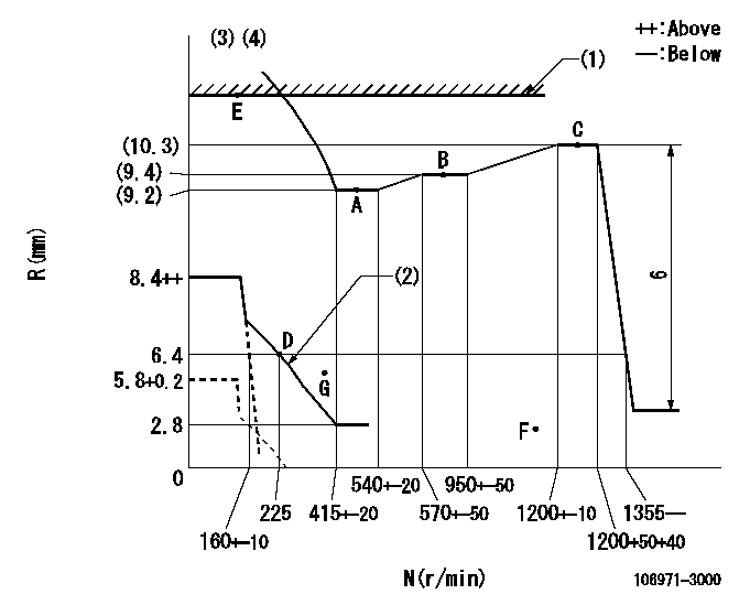
N:Pump speed
R:Rack position (mm)
(1)RACK LIMIT
(2)Beginning of damper spring operation: DL
(3)Set idle at point G (N = N1, R = R1) and confirm that the fuel injection quantity at N = N2 does not exceed F.
(4)Adjust so that the control lever's stop position is R = R2 (N = 0).
----------
DL=5.4-0.2mm N1=300r/min R1=5.4mm N2=1000r/min R2=5.8+0.2mm
----------
----------
DL=5.4-0.2mm N1=300r/min R1=5.4mm N2=1000r/min R2=5.8+0.2mm
----------
Speed control lever angle

F:Full speed
----------
----------
a=12deg+-5deg
----------
----------
a=12deg+-5deg
0000000901
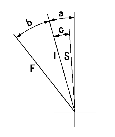
F:Full load
I:Idle
S:Stop
----------
----------
a=19deg+-5deg b=36deg+-3deg c=16deg+-3deg
----------
----------
a=19deg+-5deg b=36deg+-3deg c=16deg+-3deg
0000001501 MICRO SWITCH
Switch adjustment
Adjust the bolt so that the lower lever position is obtained when the switch is turned ON.
(1)Speed N1
(2)Rack position Ra
----------
N1=325-25r/min Ra=6.4mm
----------
----------
N1=325-25r/min Ra=6.4mm
----------
Information:
(1) Thickness of spacer plate ... 9.970 0.025 mm (.3925 .0010 in.) Thickness of spacer plate gasket ... 0.208 0.025 mm (.0082 .0010 in.) For height of liner over top of spacer plate make reference to Cylinder Liner Projection.(2) Camshaft bearing bore (installed) ... 58.80 0.06 mm (2.315 .002 in.) Bore in block for camshaft bearings ... 65.100 0.025 mm (2.5630 .0010 in.)(3) Bore in block for main bearings (standard size) ... 96.926 0.013 mm (3.8160 .0005 in.) Bore in block for main bearings 0.51 mm (.020 in.) oversize ... 97.436 0.013 mm (3.8361 .0005 in.)(4) Dimension from center of main bearing bore to top of cylinder block (new) ... 383.515 0.165 mm (15.099 .0064 in.)(5) Dimension from center of main bearing bore to bottom of cylinder block (new) ... 153.99 0.10 mm (6.063 .004 in.)(6) Torque for bolts holding bearing caps for main bearings: a. Put 2P2506 Thread Lubricant on threads and washer face.b. Tighten all bolts to ... 41 4 N m (30 3 lb ft)c. Put a mark on each bolt and cap.d. Tighten all bolts from mark ... 90 5° Install bearing caps with the part number toward the front of the engine. Be sure that the mark (number) on the bearing cap next to the bolt hole is in agreement with the mark in the cylinder block.(7) Clearance between main bearing cap and cylinder block ... 0.033 mm (.0013 in.)tight to ... 0.043 mm (.0017 in.) loose Main bearing cap width ... 165.095 0.020 mm (6.4998 .0008 in.)Width of cylinder block for main bearing cap ... 165.100 0.018 mm (6.5000 .0007 in.) (8) Piston cooling orifice.
There are holes in the bores for the main bearings, between the cylinders for piston cooler orifices. These holes must have orifices (8) installed.
(9) Distance two dowels extend from the surface of the cylinder block ... 19.8 0.5 mm (.78 .02 in.)(10) Distance hollow dowel extends from the surface of the cylinder block ... 16.0 0.5 mm (.63 .02 in.)(11) Depth to install two dowels below the surface of the cylinder block (apply loctite #11358) ... 1.0 0.5 mm (.04 .02 in.)(12) Distance dowels extend from the front face of the cylinder block ... 22.4 0.5 mm (.88 .02 in.)(13) Distance stud extends from the front face of the cylinder block ... 15.7 0.5 mm (.62 .02 in.)(14) Distance two dowels extend from the rear face of the cylinder block ... 12.7 0.5 mm (.50 .02 in.)