Information
ZEXEL
106672-9640
1066729640

Rating:
Service parts 106672-9640 INJECTION-PUMP ASSEMBLY:
1.
_
5.
AUTOM. ADVANCE MECHANIS
7.
COUPLING PLATE
8.
_
9.
_
10.
NOZZLE AND HOLDER ASSY
11.
Nozzle and Holder
12.
Open Pre:MPa(Kqf/cm2)
13.
NOZZLE-HOLDER
14.
NOZZLE
15.
NOZZLE SET
Include in #1:
106672-9640
as INJECTION-PUMP ASSEMBLY
Cross reference number
ZEXEL
106672-9640
1066729640
Zexel num
Bosch num
Firm num
Name
106672-9640
Calibration Data:
Adjustment conditions
Test oil
1404 Test oil ISO4113 or {SAEJ967d}
1404 Test oil ISO4113 or {SAEJ967d}
Test oil temperature
degC
40
40
45
Nozzle and nozzle holder
105780-8130
Bosch type code
EFEP215A
Nozzle
105780-0050
Bosch type code
DN6TD119NP1T
Nozzle holder
105780-2090
Bosch type code
EFEP215
Opening pressure
MPa
17.2
Opening pressure
kgf/cm2
175
Injection pipe
Outer diameter - inner diameter - length (mm) mm 8-3-600
Outer diameter - inner diameter - length (mm) mm 8-3-600
Overflow valve opening pressure
kPa
157
123
191
Overflow valve opening pressure
kgf/cm2
1.6
1.25
1.95
Tester oil delivery pressure
kPa
157
157
157
Tester oil delivery pressure
kgf/cm2
1.6
1.6
1.6
Direction of rotation (viewed from drive side)
Left L
Left L
Injection timing adjustment
Direction of rotation (viewed from drive side)
Left L
Left L
Injection order
1-4-2-6-
3-5
Pre-stroke
mm
2.65
2.6
2.7
Beginning of injection position
Governor side NO.1
Governor side NO.1
Difference between angles 1
Cal 1-4 deg. 60 59.5 60.5
Cal 1-4 deg. 60 59.5 60.5
Difference between angles 2
Cyl.1-2 deg. 120 119.5 120.5
Cyl.1-2 deg. 120 119.5 120.5
Difference between angles 3
Cal 1-6 deg. 180 179.5 180.5
Cal 1-6 deg. 180 179.5 180.5
Difference between angles 4
Cal 1-3 deg. 240 239.5 240.5
Cal 1-3 deg. 240 239.5 240.5
Difference between angles 5
Cal 1-5 deg. 300 299.5 300.5
Cal 1-5 deg. 300 299.5 300.5
Injection quantity adjustment
Adjusting point
A
Rack position
14.2
Pump speed
r/min
900
900
900
Average injection quantity
mm3/st.
253
250
256
Max. variation between cylinders
%
0
-3
3
Basic
*
Fixing the lever
*
Injection quantity adjustment_02
Adjusting point
B
Rack position
4.9+-0.5
Pump speed
r/min
300
300
300
Average injection quantity
mm3/st.
20
18
22
Max. variation between cylinders
%
0
-15
15
Fixing the rack
*
Test data Ex:
Governor adjustment
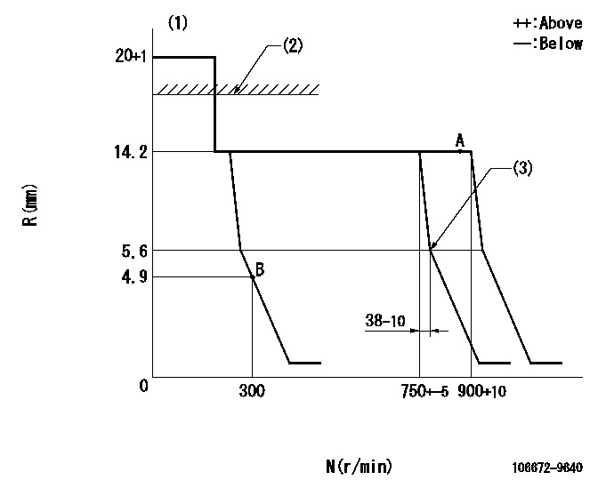
N:Pump speed
R:Rack position (mm)
(1)Target notch: K
(2)RACK LIMIT: RAL
(3)Idle sub spring setting: L1.
----------
K=17 RAL=15.2+0.2mm L1=5.6-0.5mm
----------
----------
K=17 RAL=15.2+0.2mm L1=5.6-0.5mm
----------
Speed control lever angle

F:Full speed
I:Idle
(1)Stopper bolt setting
----------
----------
a=(13deg)+-5deg b=(37deg)+-5deg
----------
----------
a=(13deg)+-5deg b=(37deg)+-5deg
Stop lever angle

N:Pump normal
S:Stop the pump.
----------
----------
a=19deg+-5deg b=53deg+-5deg
----------
----------
a=19deg+-5deg b=53deg+-5deg
Timing setting

(1)Pump vertical direction
(2)Coupling's key groove position at No 1 cylinder's beginning of injection
(3)-
(4)-
----------
----------
a=(10deg)
----------
----------
a=(10deg)
Information:
ACTION REQUIRED
Before completing this Rework Procedure, please review the safety actions in the Operation and Maintenance Manual for your machine.
Choose one of the following actions:
Before Failure: If electronic unit fuel injectors have not failed, reflash the engine ECM with the new software. The new software offers enhanced protection to the fuel system if the fuel/water separator is not drained of water when the "Water Separator Full Indicator" is displayed.
After Failure: If electronic unit fuel injectors have failed, replace the injectors and reflash the engine ECM with the new software.
For detailed instructions on removing and installing the injectors, refer to UENR0633, Disassembly and Assembly, "Electronic Unit Injector - Remove" and "Electronic Unit Injector - Install".
SERVICE CLAIM ALLOWANCES
Product smu/age whichever comes first Caterpillar Dealer Suggested Customer Suggested
Parts % Labor Hrs% Parts % Labor Hrs% Parts % Labor Hrs%
*******Group 1*******
0-3000 hrs,
0-36 mo 100.0% 100.0% 0.0% 0.0% 0.0% 0.0%
This is a 1.0-hour job for Group 1
1 hour to update the software. An additional 3 hours is allowed to replace the injectors, after failure.
Product smu/age whichever comes first Caterpillar Dealer Suggested Customer Suggested
Parts % Labor Hrs% Parts % Labor Hrs% Parts % Labor Hrs%
*******Group 2*******
0-3000 hrs,
0-36 mo 100.0% 100.0% 0.0% 0.0% 0.0% 0.0%
This is a 1.0-hour job for Group 2
1 hour to update the software. An additional 3 hours is allowed to replace the injectors, after failure.
PARTS DISPOSITION
Handle the parts in accordance with your Warranty Bulletin on warranty parts handling.
Have questions with 106672-9640?
Group cross 106672-9640 ZEXEL
Komatsu
Komatsu
Komatsu
106672-9640