Information
ZEXEL
106661-0230
1066610230
NISSAN-DIESEL
1671796004
1671796004

Rating:
Cross reference number
ZEXEL
106661-0230
1066610230
NISSAN-DIESEL
1671796004
1671796004
Zexel num
Bosch num
Firm num
Name
Calibration Data:
Adjustment conditions
Test oil
1404 Test oil ISO4113 or {SAEJ967d}
1404 Test oil ISO4113 or {SAEJ967d}
Test oil temperature
degC
40
40
45
Nozzle
105015-3100
Nozzle holder
105031-4140
Opening pressure
MPa
22.6
Opening pressure
kgf/cm2
230
Injection pipe
Outer diameter - inner diameter - length (mm) mm 6-2-500
Outer diameter - inner diameter - length (mm) mm 6-2-500
Overflow valve
132424-0620
Overflow valve opening pressure
kPa
157
123
191
Overflow valve opening pressure
kgf/cm2
1.6
1.25
1.95
Tester oil delivery pressure
kPa
157
157
157
Tester oil delivery pressure
kgf/cm2
1.6
1.6
1.6
Direction of rotation (viewed from drive side)
Right R
Right R
Injection timing adjustment
Direction of rotation (viewed from drive side)
Right R
Right R
Injection order
1-4-2-6-
3-5
Pre-stroke
mm
3.65
3.6
3.7
Beginning of injection position
Drive side NO.1
Drive side NO.1
Difference between angles 1
Cal 1-4 deg. 60 59.5 60.5
Cal 1-4 deg. 60 59.5 60.5
Difference between angles 2
Cyl.1-2 deg. 120 119.5 120.5
Cyl.1-2 deg. 120 119.5 120.5
Difference between angles 3
Cal 1-6 deg. 180 179.5 180.5
Cal 1-6 deg. 180 179.5 180.5
Difference between angles 4
Cal 1-3 deg. 240 239.5 240.5
Cal 1-3 deg. 240 239.5 240.5
Difference between angles 5
Cal 1-5 deg. 300 299.5 300.5
Cal 1-5 deg. 300 299.5 300.5
Injection quantity adjustment
Adjusting point
A
Rack position
11.3
Pump speed
r/min
850
850
850
Average injection quantity
mm3/st.
127
125
129
Max. variation between cylinders
%
0
-4
4
Fixing the lever
*
Injection quantity adjustment_02
Adjusting point
B
Rack position
11.3
Pump speed
r/min
750
750
750
Average injection quantity
mm3/st.
127
125
129
Max. variation between cylinders
%
0
-4
4
Basic
*
Fixing the lever
*
Injection quantity adjustment_03
Adjusting point
D
Rack position
6.5+-0.5
Pump speed
r/min
300
300
300
Average injection quantity
mm3/st.
17
15.3
18.7
Max. variation between cylinders
%
0
-10
10
Fixing the rack
*
Timer adjustment
Pump speed
r/min
500+-50
Advance angle
deg.
0
0
0
Remarks
Start
Start
Timer adjustment_02
Pump speed
r/min
700
Advance angle
deg.
0.75
0.4
1.1
Timer adjustment_03
Pump speed
r/min
900
Advance angle
deg.
1.25
0.9
1.6
Timer adjustment_04
Pump speed
r/min
1100+50
Advance angle
deg.
2.5
1.9
2.7
Remarks
Finish
Finish
Test data Ex:
Governor adjustment
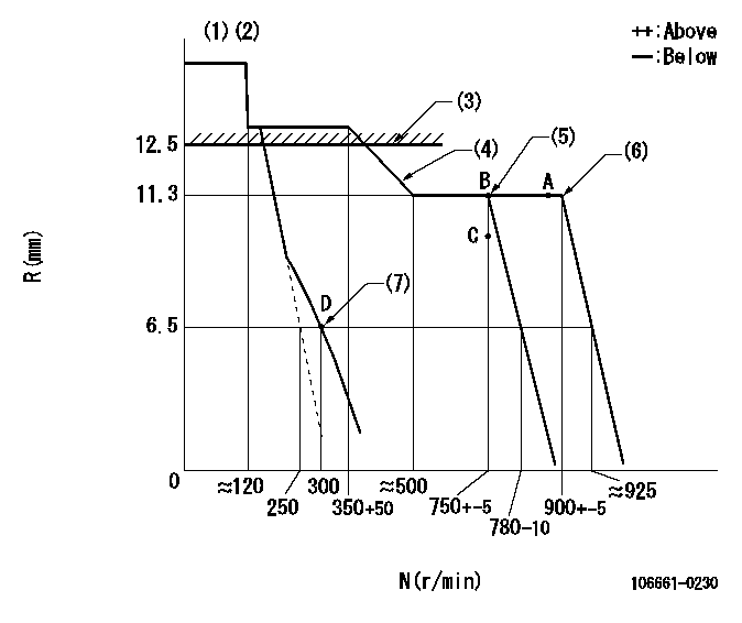
N:Pump speed
R:Rack position (mm)
(1)Target notch: K
(2)Confirm that the rack is pulled back to R = R1 or less at solenoid operation.
(3)RACK LIMIT: RAL
(4)Set the idle spring.
(5)Confirm speed droop.
(6)Set the maximum speed.
(7)Set idle sub-spring
----------
K=5 R1=4mm RAL=12.5+0.2mm
----------
----------
K=5 R1=4mm RAL=12.5+0.2mm
----------
Speed control lever angle
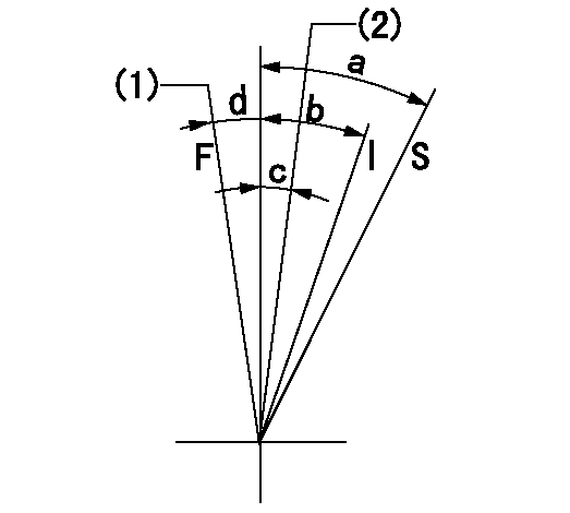
F:Full speed
I:Idle
S:Stop
(1)Pump speed = aa
(2)Pump speed = bb
----------
aa=900r/min bb=750r/min
----------
a=(32deg) b=(27deg) c=(5deg) d=(3.5deg)
----------
aa=900r/min bb=750r/min
----------
a=(32deg) b=(27deg) c=(5deg) d=(3.5deg)
Information:
Illustration 1 g00293000
Junction Box-ETR Switchgear Required (OP, WT, OS)
(1) Electronic speed switch ("ESS").
(2) Lockwire (for seal screw plugs).
(3) Identification foil.
(4) Diode ("D4").
(5) Diode ("D3").
(6) Slave relay ("SR1").
(7) Slave relay ("SR2").
(8) Emergency stop switch ("ES").
(9) Circuit breakers.
Illustration 2 g00293001
Junction Box-ETS Switchgear Not Required (OP, WT, OS)
(1) Electronic speed switch ("ESS").
(2) Lockwire (for seal screw plugs).
(3) Identification foil.
(4) Slave relay ("SR1").
(5) Emergency stop switch ("ES").
(6) Time delay relay ("TD1").
(7) Start-stop switch ("SSS").
Illustration 3 g00293002
Junction Box-ETS Switchgear Required (OP, WT, OS)
(1) Electronic speed switch ("ESS").
(2) Lockwire (for seal screw plugs).
(3) Slave relay ("SR1").
(4) Emergency stop switch ("ES").
(5) Time delay relay ("TD1").
(6) Circuit breakers.
(7) Engine mounted start-stop switch ("EMSS."
Illustration 4 g00293003
Junction Box-ETS Switchgear Not Required (OP, WT)
(1) Time delay relay ("TD2").
(2) Emergency stop switch ("ES").
(3) Identification foil.
(4) Slave relay ("SR1").
(5) Slave relay ("SR2").
(6) Time delay relay ("TD1").
(7) Circuit breakers.
Illustration 5 g00293004
Junction Box With Start-stop Switch ("SSS")
(1) Emergency stop switch ("ES").
(2) Circuit breaker reset buttons.
(3) Start-stop switch ("SSS").
Illustration 6 g00293005
(1) Power distribution box. (2) Circuit breaker reset button.
Illustration 7 g00293006
(1) Hour meter.
Illustration 8 g00293007
(1) Air starting motor. (2) Air starting valve. (3) Air supply pipe.