Information
BOSCH
F 01G 29P 00P
f01g29p00p
ZEXEL
105614-3870
1056143870

Rating:
Scheme ###:
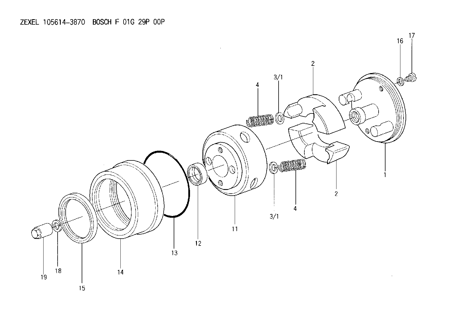
| 1. | [1] | 156133-3620 | FLYWEIGHT ASSEMBLY |
| 2. | [2] | 156108-5900 | FLYWEIGHT |
| 2. | [2] | 156108-5900 | FLYWEIGHT |
| 3/1. | [0] | 029310-9010 | SHIM D19.6&9T0.5 |
| 3/1. | [0] | 029310-9010 | SHIM D19.6&9T0.5 |
| 3/1. | [0] | 029310-9020 | SHIM D19.6&9T1 |
| 3/1. | [0] | 029310-9030 | SHIM D19.6&9T0.1 |
| 3/1. | [0] | 029310-9040 | SHIM D19.6&9T0.2 |
| 3/1. | [0] | 029310-9050 | PLAIN WASHER D19.6&9T1.5 |
| 3/1. | [0] | 139409-0000 | SHIM D19.6&9.0T0.15 |
| 4. | [2] | 156125-7200 | COMPRESSION SPRING |
| 4. | [2] | 156125-7200 | COMPRESSION SPRING |
| 11. | [1] | 156131-0820 | FLANGE BUSHING |
| 12. | [1] | 029622-8010 | PACKING RING |
| 13. | [1] | 156117-0100 | O-RING |
| 14. | [1] | 156114-1400 | CASE |
| 15. | [1] | 156116-2220 | PACKING RING |
| 16. | [2] | 026508-1240 | GASKET D11.9&8.2T1.0 |
| 17. | [2] | 156115-0100 | CAPSULE |
| 18. | [1] | 029321-4010 | LOCKING WASHER |
| 19. | [1] | 131325-0400 | UNION NUT |
Include in #1:
101608-9280
as AUTOM. ADVANCE MECHANIS
Cross reference number
Zexel num
Bosch num
Firm num
Name
Information:
Do not turn the crankshaft while any of the connecting rods are in the engine without the caps installed.
1. Remove the carbon from the top inside surface of the cylinder liners.2. Turn the crankshaft until two pistons are at bottom center.3. Remove bearing caps (1) from the two connecting rods. 4. Push the pistons up until the piston rings are clear of the cylinder liner. Remove pistons (2). Keep each cap with its connecting rod.5. Do Steps 1 through 4 for the remainder of the pistons.Install Pistons & Connecting Rods
1. Put clean engine oil on the piston rings, connecting rod bearings and cylinder liners. 2. Put two pistons in position opposite of each other in the correct bore of the block. Install pistons (1) with Tool (A).
Make sure that the pistons are installed with flat surfaces (2) of the connecting rods toward each other and the chamfered sides (4) toward the crankshaft.
For more detail about the installation of connecting rod bearings, see Remove & Install Connecting Rod Bearings.
Do not use an impact wrench to tighten the nuts the additional 120 degrees when the bearing clearance is checked.
3. Check the bearing clearances with Plastigage.4. Put 2P-2506 Thread Lubricant on bolts (5). Install caps (3) and the nuts finger tight. Tighten each nut to a torque of 81 8 N m (60 6 lb ft). Put a mark across the nuts and bolts. Tighten each nut 120 degrees more.5. Check the side clearance between two connecting rods on the same crankshaft journal. The clearance must be 0.28 to 0.84 mm (.011 to .033 in) for new rods.6. Do Steps 1 through 5 for the remainder of the pistons.End By:a. install piston cooling tubesb. install oil pumpc. install cylinder headsDisassemble & Assemble Pistons & Connecting Rods
Start By:a. remove pistons and connecting rods 1. Remove bearings (3) from the connecting rod and connecting rod cap. The new style retainer rings allow the use of pliers to remove retainer ring (1).2. Remove retainer ring (1) with Tool (A) or pliers.3. Remove pin (2) and connecting rod (4) from the pistons. 4. Remove piston rings (5) from the piston with Tool (B). Clean the piston ring grooves on the pistons with an acceptable ring groove cleaning tool. See Use Of Piston Pin Bearing Removal & Installation Tools, Special Instructions, SMHS7295-02.5. Heat connecting rod (4) in an oven to a temperature of 177° to 260° C (350° to 500° F). Never use a direct flame to heat a connecting rod. 6. Put connecting rod (4) in position on the base plate of Tooling (C). Put a new rod pin bearing (6) on the adapter part of Tooling (C). The old bearing is pushed out by Tooling (C) as the new bearing is installed.7. Use Tooling (C) to push the new bearing into the connecting rod until the push adapter of Tooling (C) makes full contact with the connecting rod surface.8. Use a pin boring machine to make the rod pin bearing the