Information
BOSCH
9 420 610 061
9420610061
ZEXEL
105520-3111
1055203111

Rating:
Scheme ###:
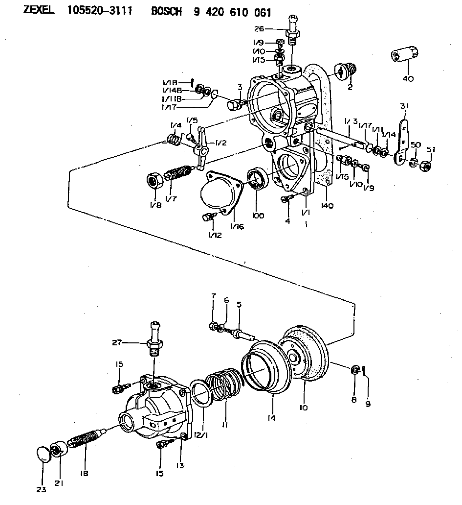
| 1. | [1] | 155000-6720 | GOVERNOR HOUSING |
| 1/1. | [1] | 155001-6120 | GOVERNOR HOUSING |
| 1/2. | [1] | 155003-0600 | CONTROL LEVER |
| 1/3. | [1] | 155004-0900 | LEVER SHAFT |
| 1/4. | [1] | 155005-0200 | COILED SPRING |
| 1/5. | [1] | 155006-0700 | BLEEDER SCREW |
| 1/7. | [1] | 155007-0220 | HEADLESS SCREW |
| 1/8. | [1] | 155011-0200 | HEXAGON NUT |
| 1/9. | [2] | 029010-6010 | CAPSULE M6P1.0L7 |
| 1/9. | [2] | 029010-6010 | CAPSULE M6P1.0L7 |
| 1/10. | [2] | 026506-1040 | GASKET D9.9&6.2T1 |
| 1/10. | [2] | 026506-1040 | GASKET D9.9&6.2T1 |
| 1/11. | [0] | 029310-8010 | PLAIN WASHER D15&8.4T0.2 |
| 1/11B. | [0] | 029310-8020 | PLAIN WASHER D15&8.4T0.3 |
| 1/12. | [3] | 029010-6680 | BLEEDER SCREW |
| 1/14. | [2] | 029300-8010 | PLAIN WASHER D15&8T1.00 |
| 1/14B. | [0] | 029300-8030 | PLAIN WASHER D15&8T1.50 |
| 1/15. | [2] | 155012-0100 | ADAPTOR |
| 1/15. | [2] | 155012-0100 | ADAPTOR |
| 1/16. | [1] | 155013-0100 | CAP |
| 1/17. | [2] | 029630-8060 | O-RING |
| 1/17. | [2] | 029630-8060 | O-RING |
| 1/18. | [2] | 025520-1210 | SPLIT PIN |
| 2. | [1] | 154007-0200 | ADAPTOR |
| 3. | [1] | 020018-1840 | BLEEDER SCREW M8P1.25L18 |
| 4. | [4] | 021006-1540 | FLAT-HEAD SCREW |
| 5. | [1] | 153406-0400 | BLEEDER SCREW |
| 6. | [1] | 014110-5440 | LOCKING WASHER |
| 7. | [1] | 013020-5220 | UNION NUT M5P0.8H4 |
| 8. | [1] | 023500-6210 | PLAIN WASHER D11&6.4T1.5 |
| 9. | [1] | 025520-1210 | SPLIT PIN |
| 10. | [1] | 155020-1220 | DIAPHRAGM |
| 11. | [1] | 155032-0100 | GOVERNOR SPRING |
| 12/1. | [0] | 155407-1100 | SHIM D37&30.5T0.5 |
| 12/1. | [0] | 155407-1200 | SHIM D37&30.5T1.0 |
| 12/1. | [0] | 155407-1300 | SHIM D37&30.5T1.5 |
| 12/1. | [0] | 155407-1400 | SHIM D37&30.5T2.0 |
| 12/1. | [0] | 155407-1500 | SHIM D37&30.5T2.5 |
| 12/1. | [0] | 155407-1600 | SHIM D37&30.5T3.0 |
| 12/1. | [0] | 155407-1700 | SHIM D37&30.5T0.2 |
| 12/1. | [0] | 155407-1800 | SHIM D37&30.5T0.3 |
| 13. | [1] | 155240-0500 | COVER |
| 14. | [1] | 155019-0220 | FILLER PIECE |
| 15. | [4] | 020105-1640 | BLEEDER SCREW M5P0.8L16 |
| 15. | [4] | 020105-1640 | BLEEDER SCREW M5P0.8L16 |
| 18. | [1] | 155241-2220 | HEADLESS SCREW |
| 21. | [1] | 155245-0100 | HEXAGON NUT |
| 23. | [1] | 029142-0010 | CAPSULE |
| 26. | [1] | 029721-2050 | JOINT CONNECTION |
| 27. | [1] | 029721-2040 | JOINT CONNECTION |
| 31. | [1] | 155414-5500 | CONTROL LEVER |
| 40. | [1] | 155404-3700 | CAP |
| 50. | [1] | 014110-8440 | LOCKING WASHER |
| 51. | [1] | 013020-8040 | UNION NUT M8P1.25H7 |
| 100. | [1] | 029621-7010 | PACKING RING |
| 140. | [1] | 154390-0000 | GASKET |
Include in #1:
101433-9210
as GOVERNOR
Cross reference number
Zexel num
Bosch num
Firm num
Name
105520-3111
9 420 610 061
* K
Information:
Disassembly and Reassembly of General Parts
Oil seals
When installing oil seals, observe the following.Installation of Oil Seals to Housings
(a) Check the seal lip for scratches and damage, and be sure to position the lip correctly.(b) Apply a small amount of grease to the periphery (housing contact surface) of the oil seal before installation.(c) Use an oil seal driver that guides the seal lip and presses the seal periphery, as shown in the diagram on the right. Striking the oil seal directly with a hammer causes seal damage and results in oil leaks.
Oil seal driverInstallation of Oil Seals to Shafts
(a) Apply grease to the oil seal lip.(b) Use an oil seal guide similar to the one shown in the diagram when installing an oil seal over the stepped portion, splines, threads or key grooves.
Oil seal guideO-rings
Use an O-ring guide similar to the one shown in the diagram when installing an O-ring over the stepped portion, splines, threads or key grooves. Be sure to apply a small amount of grease to the O-ring before installation.
O-ring guideBearings
(1) When installing a bearing, be sure to push the inner or outer race that fits into the installation position. (When the inner race fits into the installation position, push the inner race into position. When the outer race fits into the installation position, push the outer race into position.) Be sure to use a bearing driver similar to the one shown in the diagram.
Bearing driver(2) Use of a press minimizes the impact on the bearing and ensures proper installation.
Using press for bearing installationLock Plates
Be sure to bend lock plates. The diagram on the right shows the methods of bending representative lock plates.
Bending lock plateSplit Pins and Spring Pins
Generally, new split pins should be installed whenever split pins are removed. Be sure to bend split pins. Be sure to check spring pins for secure installation.
Have questions with 105520-3111?
Group cross 105520-3111 ZEXEL
Isuzu
Nissan
Nissan-Diesel
105520-3111
9 420 610 061