Information
BOSCH
F 01G 29N 0G2
f01g29n0g2
ZEXEL
105448-9900
1054489900

Rating:
Scheme ###:
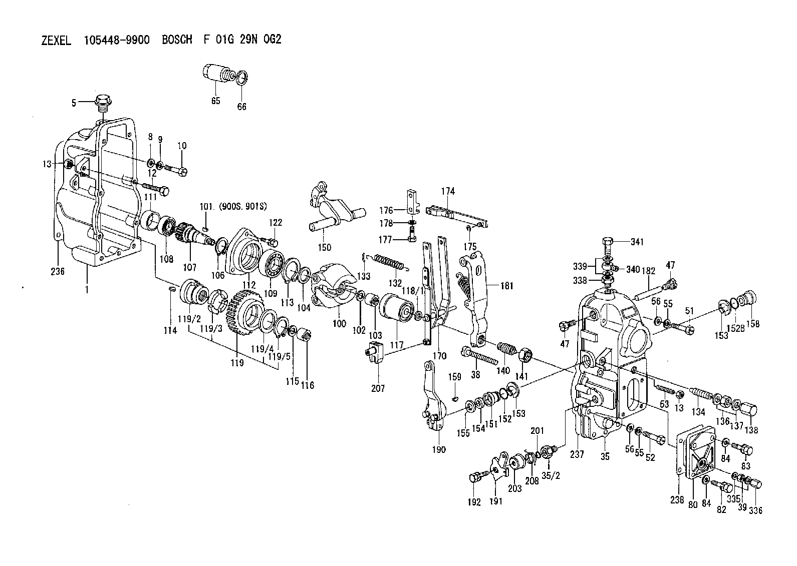
| 1. | [1] | 154002-2920 | GOVERNOR HOUSING |
| 5. | [1] | 154007-1600 | CAPSULE |
| 8. | [9] | 029300-6040 | PLAIN WASHER |
| 9. | [9] | 029320-6010 | LOCKING WASHER |
| 10. | [9] | 029000-6490 | BLEEDER SCREW |
| 12. | [1] | 154010-3900 | BLEEDER SCREW |
| 13. | [2] | 154011-0100 | HEXAGON NUT |
| 13. | [2] | 154011-0100 | HEXAGON NUT |
| 35. | [1] | 154520-7520 | GOVERNOR COVER |
| 35/2. | [1] | 154321-0200 | BUSHING |
| 38. | [1] | 154031-3000 | FLAT-HEAD SCREW |
| 39. | [1] | 013020-6040 | UNION NUT |
| 47. | [2] | 154036-0300 | CAPSULE |
| 47. | [2] | 154036-0300 | CAPSULE |
| 51. | [4] | 029000-6470 | BLEEDER SCREW |
| 52. | [5] | 029000-6480 | BLEEDER SCREW |
| 53. | [1] | 154010-0200 | FLAT-HEAD SCREW |
| 55. | [9] | 029320-6010 | LOCKING WASHER |
| 55. | [9] | 029320-6010 | LOCKING WASHER |
| 56. | [9] | 029300-6040 | PLAIN WASHER |
| 56. | [9] | 029300-6040 | PLAIN WASHER |
| 65. | [1] | 154050-3900 | CAP |
| 66. | [1] | 029332-0050 | GASKET |
| 80. | [1] | 154063-0900 | COVER |
| 82. | [2] | 029020-6210 | BLEEDER SCREW |
| 83. | [2] | 029020-6210 | BLEEDER SCREW |
| 84. | [4] | 029300-6040 | PLAIN WASHER |
| 84. | [4] | 029300-6040 | PLAIN WASHER |
| 100. | [1] | 154100-9720 | FLYWEIGHT ASSEMBLY |
| 101. | [1] | 025803-1610 | WOODRUFF KEY 16 MM |
| 102. | [1] | 029321-2020 | LOCKING WASHER |
| 103. | [1] | 029231-2030 | UNION NUT |
| 104. | [1] | 154120-0100 | PLAIN WASHER |
| 106. | [1] | 029602-0020 | LOCKING WASHER |
| 107. | [1] | 154121-0400 | TOOTHED GEAR |
| 108. | [1] | 016610-2640 | BEARING PLATE |
| 109. | [1] | 028102-0010 | BEARING PLATE |
| 111. | [1] | 154134-0000 | SPACER BUSHING |
| 112. | [1] | 154122-0300 | COVER |
| 113. | [1] | 029614-7020 | LOCKING WASHER |
| 114. | [1] | 025803-1310 | WOODRUFF KEY 13 MM |
| 115. | [1] | 029321-2020 | LOCKING WASHER |
| 116. | [1] | 029231-2030 | UNION NUT |
| 117. | [1] | 154123-1920 | SLIDING PIECE |
| 118/1. | [0] | 029311-0010 | SHIM D14&10.1T0.2 |
| 118/1. | [0] | 029311-0180 | SHIM D14&10.1T0.3 |
| 118/1. | [0] | 029311-0190 | SHIM D14&10.1T0.40 |
| 118/1. | [0] | 029311-0210 | SHIM D14&10.1T1 |
| 118/1. | [0] | 139410-0000 | SHIM D14&10.1T0.5 |
| 118/1. | [0] | 139410-0100 | SHIM D14&10.1T1.5 |
| 118/1. | [0] | 139410-3000 | SHIM D14&10.1T2.0 |
| 118/1. | [0] | 139410-3100 | SHIM D14&10.1T3.0 |
| 118/1. | [0] | 139410-3200 | SHIM D14&10.1T4.0 |
| 119. | [1] | 154130-1720 | TOOTHED GEAR |
| 119/2. | [1] | 154132-0320 | HOLDER |
| 119/3. | [4] | 153251-0100 | DAMPER |
| 119/4. | [1] | 139329-0000 | PLAIN WASHER |
| 119/5. | [1] | 016020-2810 | LOCKING WASHER |
| 122. | [3] | 020106-2840 | BLEEDER SCREW |
| 132. | [1] | 154154-0900 | COILED SPRING |
| 133. | [2] | 154156-0100 | TUBE |
| 134. | [1] | 154158-0620 | HEADLESS SCREW |
| 136. | [1] | 029201-2290 | UNION NUT |
| 137. | [2] | 026512-1640 | GASKET |
| 138. | [1] | 154159-1200 | CAP NUT |
| 140. | [1] | 154170-0220 | HEADLESS SCREW |
| 141. | [1] | 029201-6010 | UNION NUT |
| 150. | [1] | 154200-4520 | SWIVELLING LEVER |
| 151. | [1] | 154204-4100 | BUSHING |
| 152. | [1] | 139718-0200 | O-RING |
| 152B. | [1] | 139716-0100 | O-RING |
| 153. | [2] | 016010-1640 | LOCKING WASHER |
| 153. | [2] | 016010-1640 | LOCKING WASHER |
| 154. | [1] | 139611-0200 | PACKING RING |
| 155. | [1] | 029311-1010 | SHIM |
| 158. | [1] | 154204-2200 | BUSHING |
| 159. | [1] | 025803-1310 | WOODRUFF KEY 13 MM |
| 170. | [1] | 154211-5220 | FORK LEVER |
| 174. | [1] | 154230-1820 | STRAP |
| 175. | [1] | 016010-0540 | LOCKING WASHER |
| 176. | [1] | 154232-0500 | CONNECTOR |
| 177. | [1] | 154316-2300 | BLEEDER SCREW |
| 178. | [1] | 029320-6010 | LOCKING WASHER |
| 181. | [1] | 154236-5821 | TENSIONING LEVER |
| 182. | [1] | 154237-0200 | BEARING PIN |
| 190. | [1] | 154345-1520 | CONTROL LEVER |
| 191. | [1] | 154304-1120 | CONTROL LEVER |
| 192. | [1] | 020006-1640 | BLEEDER SCREW |
| 201. | [1] | 139710-0400 | O-RING |
| 203. | [1] | 154322-0100 | CAP |
| 207. | [1] | 154326-5020 | CONTROL LEVER |
| 208. | [1] | 154327-7600 | COILED SPRING |
| 236. | [1] | 154390-2900 | GASKET |
| 237. | [1] | 154390-3100 | GASKET |
| 238. | [1] | 154390-3500 | GASKET |
| 335. | [2] | 026506-1040 | GASKET |
| 336. | [1] | 154035-1600 | CAP NUT |
| 338. | [1] | 131002-3800 | ADAPTOR |
| 339. | [2] | 029341-2140 | GASKET |
| 340. | [1] | 029711-2350 | INLET UNION |
| 341. | [1] | 029731-2240 | EYE BOLT |
| 900S. | [1] | 025803-1310 | WOODRUFF KEY 13 MM |
| 901S. | [1] | 025803-1610 | WOODRUFF KEY 16 MM |
Include in #1:
106672-4552
as GOVERNOR
Cross reference number
Zexel num
Bosch num
Firm num
Name
Information:
Retrofit DPF (Diesel Particulate Filter) System
This Retrofit DPF (Diesel Particulate Filter) System must have the following components:
Diesel Particulate Filter (DPF)
Silencer and/or housing
Clamp and gasket
Flow direction label
Engine tagEngine exhaust flows into the Retrofit DPF System reactor housing through the exhaust inlet. Exhaust flows through the DPF.Non-Unidirectional Requirements
(r) Directional Requirements for Diesel Emission Control Strategies
Every diesel emission control strategy must be installed as designed and specified by the manufacturer. For a diesel emission control strategy comprised of multiple exhaust aftertreatment parts, each aftertreatment part must be installed in the proper order relative to the exhaust flow.
Diesel emission control strategies installed between February 19, 2009, and January 1, 2010.
(A) The diesel emission control strategy must indicate the proper direction of exhaust flow. This exhaust flow indicator will allow the end user or installer to see how to install the device properly.
Diesel emission control strategies installed on or after January 1, 2010.
(A) The proper direction for exhaust to flow through the aftertreatment part of the diesel emission control strategy is to be clearly indicated on the outside surface of the aftertreatment part. The exhaust flow indicator consists of an arrow imprinted on or affixed to the aftertreatment part. The indicator arrow is to be clearly visible and durable.
(B) The aftertreatment part must be constructed such that the part can only be installed into the diesel emission control strategy in one unique direction relative to the exhaust flow. The aftertreatment part cannot be installed in the reversed direction.
(C) A diesel emission control strategy not meeting these requirements may be installed after January 1, 2010, if the diesel emission controls strategy: (1) Has a date of manufacture no later than December 31, 2009, (2) Complies with (r)(1) and (r)(2) above and (3) Is installed no later than December 31 2011.
(D) Except for an aftertreatment part that reduces PM through a physical trapping mechanism, such as a diesel particulate filter, the applicant may request that the Executive Officer waives the requirements that an aftertreatment part indicates the flow direction and have unidirectional construction. In reviewing the request, the Executive Officer may consider all relevant information including, but not limited to, the symmetry of the aftertreatment part, potential for impaired performance as a result of different orientations relative to exhaust flow, and interaction with other parts.Diesel Particulate Filter Operation
The Cat DPF is a catalyzed diesel particulate filter that is designed to reduce emissions of particulate (smoke), carbon monoxide (CO) and hydrocarbons (HC), from diesel engines. Carbon monoxide and hydrocarbon reductions are achieved when the exhaust gases interact with the catalyst on the ceramic filter. The catalyst is impregnated on the walls of the ceramic substrate. As the exhaust gases come in contact with the catalyst, a chemical reaction takes place that oxidizes the gases. The oxidation process turns carbon monoxide into carbon dioxide, and hydrocarbons into water and carbon dioxide.Reduction of Emissions
The Cat DPF is a complete product for reducing carbon monoxide, hydrocarbons, and PM. The filter is catalyzed with a precious-metal catalyst. For CO