Information
BOSCH
F 01G 29N 0JW
f01g29n0jw
ZEXEL
105447-2590
1054472590

Rating:
Scheme ###:
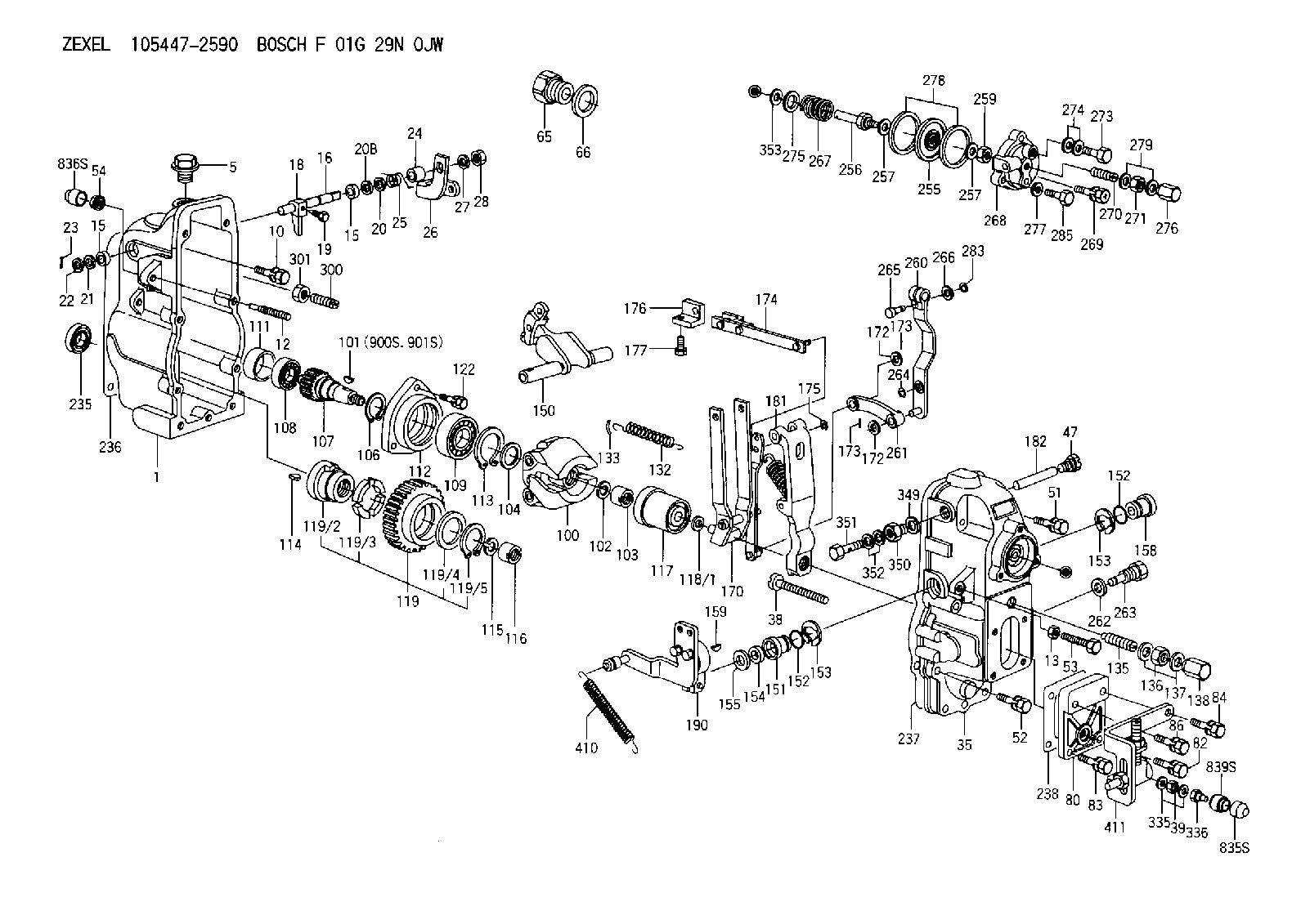
| 1. | [1] | 154002-4620 | GOVERNOR HOUSING |
| 5. | [1] | 154007-1600 | CAPSULE |
| 10. | [8] | 139006-4100 | BLEEDER SCREW |
| 12. | [1] | 154013-8300 | FLAT-HEAD SCREW |
| 13. | [1] | 154011-4900 | UNION NUT |
| 15. | [2] | 139608-0200 | PACKING RING |
| 15. | [2] | 139608-0200 | PACKING RING |
| 16. | [1] | 155004-4900 | LEVER SHAFT |
| 18. | [1] | 155003-3100 | CONTROL LEVER |
| 19. | [1] | 155006-0700 | BLEEDER SCREW |
| 20. | [1] | 139308-0900 | PLAIN WASHER D16&8T1 |
| 20B. | [1] | 139308-1000 | PLAIN WASHER D16&8T1.5 |
| 20C. | [1] | 139408-1500 | SHIM D16&8T0.5 |
| 21. | [0] | 029310-8050 | SHIM D13.5&8T0.5 |
| 22. | [0] | 029310-8050 | SHIM D13.5&8T0.5 |
| 23. | [1] | 025520-1210 | SPLIT PIN |
| 24. | [1] | 154206-6300 | BUSHING |
| 25. | [1] | 154327-4200 | COILED SPRING |
| 26. | [1] | 154380-1900 | CONTROL LEVER |
| 27. | [1] | 014110-8440 | LOCKING WASHER D15.4&8.2T2 |
| 28. | [1] | 013020-8040 | UNION NUT |
| 35. | [1] | 154520-6520 | GOVERNOR COVER |
| 38. | [1] | 154031-3000 | FLAT-HEAD SCREW |
| 39. | [1] | 139206-0600 | UNION NUT |
| 47. | [1] | 154036-0300 | CAPSULE |
| 51. | [4] | 020106-5040 | BLEEDER SCREW |
| 52. | [3] | 020106-2840 | BLEEDER SCREW |
| 53. | [1] | 154034-0800 | BLEEDER SCREW |
| 54. | [1] | 154011-0100 | HEXAGON NUT |
| 65. | [1] | 155404-1700 | CAP |
| 66. | [1] | 026524-3040 | GASKET |
| 80. | [1] | 154063-8200 | COVER |
| 82. | [1] | 020006-1640 | BLEEDER SCREW |
| 83. | [1] | 020006-2040 | BLEEDER SCREW |
| 84. | [1] | 020006-2040 | BLEEDER SCREW |
| 86. | [1] | 020006-2040 | BLEEDER SCREW |
| 100. | [1] | 154100-9920 | FLYWEIGHT ASSEMBLY |
| 101. | [1] | 025803-1610 | WOODRUFF KEY 16 MM |
| 102. | [1] | 029321-2020 | LOCKING WASHER |
| 103. | [1] | 029231-2030 | UNION NUT |
| 104. | [1] | 154120-0100 | PLAIN WASHER |
| 106. | [1] | 029602-0020 | LOCKING WASHER |
| 107. | [1] | 154121-0400 | TOOTHED GEAR |
| 108. | [1] | 016610-2640 | BEARING PLATE |
| 109. | [1] | 028102-0010 | BEARING PLATE |
| 111. | [1] | 154134-0000 | SPACER BUSHING |
| 112. | [1] | 154122-0300 | COVER |
| 113. | [1] | 029614-7020 | LOCKING WASHER |
| 114. | [1] | 025803-1310 | WOODRUFF KEY 13 MM |
| 115. | [1] | 029321-2020 | LOCKING WASHER |
| 116. | [1] | 029231-2030 | UNION NUT |
| 117. | [1] | 154123-1920 | SLIDING PIECE |
| 118/1. | [0] | 029311-0010 | SHIM D14&10.1T0.2 |
| 118/1. | [0] | 029311-0180 | SHIM D14&10.1T0.3 |
| 118/1. | [0] | 029311-0190 | SHIM D14&10.1T0.40 |
| 118/1. | [0] | 029311-0210 | SHIM D14&10.1T1 |
| 118/1. | [0] | 139410-0000 | SHIM D14&10.1T0.5 |
| 118/1. | [0] | 139410-0100 | SHIM D14&10.1T1.5 |
| 118/1. | [0] | 139410-3000 | SHIM D14&10.1T2.0 |
| 118/1. | [0] | 139410-3100 | SHIM D14&10.1T3.0 |
| 118/1. | [0] | 139410-3200 | SHIM D14&10.1T4.0 |
| 119. | [1] | 154130-1720 | TOOTHED GEAR |
| 119/2. | [1] | 154132-0320 | HOLDER |
| 119/3. | [4] | 153251-0100 | DAMPER |
| 119/4. | [1] | 139329-0000 | PLAIN WASHER |
| 119/5. | [1] | 016020-2810 | LOCKING WASHER |
| 122. | [3] | 020106-2840 | BLEEDER SCREW |
| 132. | [1] | 154154-0900 | COILED SPRING |
| 133. | [2] | 154156-0100 | TUBE |
| 135. | [1] | 154158-4320 | HEADLESS SCREW |
| 136. | [1] | 029201-2140 | UNION NUT |
| 137. | [2] | 026512-1540 | GASKET |
| 138. | [1] | 154159-1200 | CAP NUT |
| 150. | [1] | 154200-4520 | SWIVELLING LEVER |
| 151. | [1] | 154204-2100 | BUSHING |
| 152. | [2] | 139716-0100 | O-RING |
| 152. | [2] | 139716-0100 | O-RING |
| 153. | [2] | 016010-1640 | LOCKING WASHER |
| 153. | [2] | 016010-1640 | LOCKING WASHER |
| 154. | [1] | 139611-0200 | PACKING RING |
| 155. | [1] | 029311-1010 | SHIM |
| 158. | [1] | 154204-2200 | BUSHING |
| 159. | [1] | 025803-1310 | WOODRUFF KEY 13 MM |
| 170. | [1] | 154217-2820 | FORK LEVER |
| 172. | [3] | 029310-5170 | SHIM |
| 172. | [3] | 029310-5170 | SHIM |
| 173. | [2] | 025520-1210 | SPLIT PIN |
| 173. | [2] | 025520-1210 | SPLIT PIN |
| 174. | [1] | 154234-9220 | STRAP |
| 175. | [1] | 016010-0540 | LOCKING WASHER |
| 176. | [1] | 154232-2700 | CONNECTOR |
| 177. | [2] | 029050-5040 | FLAT-HEAD SCREW |
| 181. | [1] | 154239-2720 | TENSIONING LEVER |
| 182. | [1] | 154237-1500 | BEARING PIN |
| 190. | [1] | 154349-6520 | CONTROL LEVER |
| 235. | [1] | 029621-7010 | PACKING RING |
| 236. | [1] | 154371-5600 | GASKET |
| 237. | [1] | 154371-3500 | GASKET |
| 238. | [1] | 154390-3500 | GASKET |
| 255. | [1] | 154400-7420 | DIAPHRAGM |
| 256. | [1] | 154400-4800 | STOP PIN |
| 257. | [2] | 029330-8050 | GASKET |
| 257. | [2] | 029330-8050 | GASKET |
| 259. | [1] | 154372-7200 | HEXAGON NUT |
| 260. | [1] | 154401-4420 | CONTROL LEVER |
| 261. | [1] | 154401-1020 | STRAP |
| 262. | [1] | 026510-1440 | GASKET |
| 263. | [1] | 154401-4500 | BLEEDER SCREW |
| 264. | [1] | 016010-0540 | LOCKING WASHER |
| 265. | [1] | 154222-6200 | BEARING PIN |
| 266. | [1] | 029300-4010 | PLAIN WASHER |
| 267. | [1] | 154416-2400 | COILED SPRING |
| 268. | [1] | 154404-5000 | COVER |
| 269. | [2] | 020106-2240 | BLEEDER SCREW |
| 270. | [1] | 154034-1900 | FLAT-HEAD SCREW |
| 271. | [1] | 013030-6040 | UNION NUT |
| 273. | [1] | 029731-0120 | EYE BOLT |
| 274. | [2] | 029341-0110 | GASKET |
| 275. | [0] | 029312-0180 | SHIM D25.5&20T0.5 |
| 275B. | [0] | 029312-0210 | SHIM D25.5&20T0.2 |
| 276. | [1] | 154035-1600 | CAP NUT |
| 277. | [1] | 029320-6010 | LOCKING WASHER |
| 278. | [2] | 154413-2600 | GASKET |
| 279. | [2] | 026506-1040 | GASKET |
| 283. | [1] | 016010-0440 | LOCKING WASHER |
| 285. | [1] | 029010-6310 | BLEEDER SCREW |
| 300. | [1] | 154010-0300 | FLAT-HEAD SCREW M8.P1.25.L40 |
| 301. | [1] | 154011-0100 | HEXAGON NUT |
| 335. | [2] | 026506-1040 | GASKET |
| 336. | [1] | 154035-2800 | CAP NUT |
| 349. | [1] | 026510-1340 | GASKET |
| 350. | [1] | 154036-1600 | ADAPTOR |
| 351. | [1] | 139806-0000 | EYE BOLT |
| 352. | [2] | 029340-6120 | GASKET |
| 353. | [1] | 029310-9080 | SHIM |
| 410. | [1] | 154332-3100 | COILED SPRING |
| 411. | [1] | 154373-3720 | BRACKET |
| 835S. | [1] | 154062-4020 | CAP |
| 836S. | [1] | 154062-3520 | CAP |
| 839S. | [1] | 154062-3800 | ADAPTOR |
| 900S. | [1] | 025803-1310 | WOODRUFF KEY 13 MM |
| 901S. | [1] | 025803-1610 | WOODRUFF KEY 16 MM |
Cross reference number
Zexel num
Bosch num
Firm num
Name
Information:
Illustration 2 g01681836
(3) CGI flex pipe
Inspect the CGI flex pipe that is installed on all Kenworth and Peterbilt chassis. Check for a previous update to the CGI flex pipe under either a Peterbilt or Kenworth Technical Information BulletinThis work should be charged to your local OEM dealer with instructions that are provided with the service letter.
Peterbilt -Field Repair Notice 408-1 or newer Clean Gas Induction (CGI) and Main Exhaust Pipe Couplings
Kenworth – Technical Information Bulletin Number 43-12 or newer
Drain and save the coolant. The saved coolant can then be reused. Draining the coolant is necessary in order to replace the ARD combustion head.
Illustration 3 g01678253
(4) CGI coolant hose and clamps that are replaced on S/N:SDP1-17026
Inspect the CGI coolant hose and clamps and replace the CGI coolant hose and clamps if it is necessary on S/N:SDP1-17026.
Only replace the hose if the hose has not already been updated. Only black colored hoses should be replaced. The replacement hose is blue or green in color. The blue or green hose does not need to be replaced.Note: There will be some coolant that is left in the line after draining.
Illustration 4 g01678273
(5) Location of fuel control valves
Replace the Pilot and Main Fuel Control Valves. The fuel control valve must not be overtorqued.Torque for the two solenoid valve groups ... 50 5 N m (37 4 lb ft)Final installation torque for the two solenoid nuts ... 20 3 N m (15 2 lb ft)
Replace the ARD combustion head and the components of the ARD utilizing the Disassembly and Assembly Manual, RENR9706 for the proper procedure.Note: Do not install the fuel lines to the ARD Combustion head at this time. These lines will be installed after flushing the fuel system. Leave the protective shipping caps in the fuel ports of the ARD combustion head.
Illustration 5 g01681795
(8) ARD flame detection temperature sensor
In addition to the replacement of the ARD combustion head, install a new ARD flame detection temperature sensor. Refer to Special Instruction, REHS3794 for proper wire routing. If a stainless steel zip tie is removed a newstainless steel zip tie should be used.
Illustration 6 g01681813
(9) CGI temperature sensor
Replace the CGI temperature sensor. Refer to the Disassembly and Assembly Manual, RENR9706 and Disassembly and Assembly Manual, RENR9705 for the proper procedures. Proper wire routing should be followed. If a stainless steel zip tie is removed a new stainless steel zip tie should be used.
Refill the cooling system with the coolant that was saved in Step 8.
Flush the ARD fuel system. Refer to Special Instruction, REHS3848 for the correct procedure.
Flash the engine with the latest software. The release date of the software must be November 2008 or a newer date.Tables that are used in order to look up software and the process for obtaining the software are provided below.
Perform a verification test of the air system and save the file.Note: Refer to Troubleshooting Guide, RENR9343, "Air System Verification Test" that is located on the Service Information System for the pass or fail criteria.
Perform a stationary regeneration. Check