Information
BOSCH
F 01G 29N 0LL
f01g29n0ll
ZEXEL
105447-1571
1054471571

Rating:
Scheme ###:
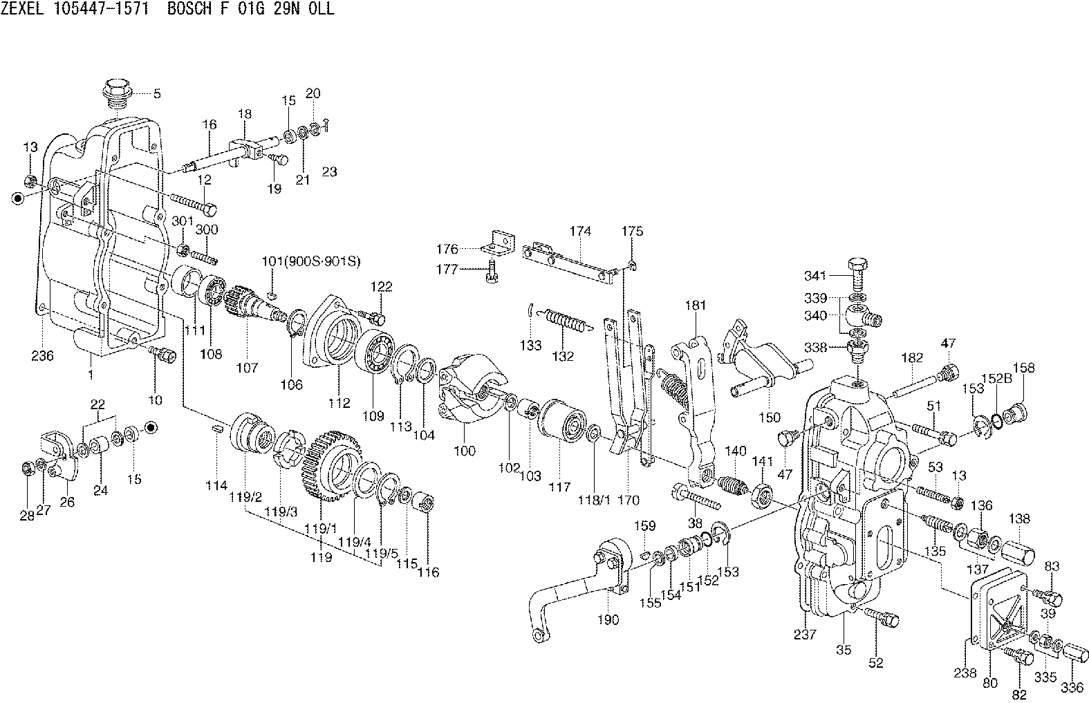
| 1. | [1] | 154002-3520 | GOVERNOR HOUSING |
| 5. | [1] | 154007-1600 | CAPSULE |
| 10. | [8] | 139006-4100 | BLEEDER SCREW |
| 12. | [1] | 154013-3200 | BLEEDER SCREW |
| 13. | [2] | 154011-0100 | HEXAGON NUT |
| 13. | [2] | 154011-0100 | HEXAGON NUT |
| 15. | [2] | 139608-0200 | PACKING RING |
| 15. | [2] | 139608-0200 | PACKING RING |
| 16. | [1] | 155004-4900 | LEVER SHAFT |
| 18. | [1] | 155003-3100 | CONTROL LEVER |
| 19. | [1] | 155006-0700 | BLEEDER SCREW |
| 20. | [1] | 139308-1100 | PLAIN WASHER |
| 21. | [0] | 029310-8050 | SHIM D13.5&8T0.5 |
| 22. | [0] | 029310-8050 | SHIM D13.5&8T0.5 |
| 23. | [1] | 155402-3800 | SAFETY PIN |
| 24. | [1] | 154206-2000 | BUSHING |
| 26. | [1] | 154381-9820 | CONTROL LEVER |
| 27. | [1] | 014110-8440 | LOCKING WASHER D15.4&8.2T2 |
| 28. | [1] | 013020-8040 | UNION NUT |
| 35. | [1] | 154520-7220 | GOVERNOR COVER |
| 38. | [1] | 154031-3000 | FLAT-HEAD SCREW |
| 39. | [1] | 139206-0600 | UNION NUT |
| 47. | [2] | 154036-0300 | CAPSULE |
| 47. | [2] | 154036-0300 | CAPSULE |
| 51. | [4] | 020106-5040 | BLEEDER SCREW |
| 52. | [3] | 020106-2840 | BLEEDER SCREW |
| 53. | [1] | 154010-0300 | FLAT-HEAD SCREW M8.P1.25.L40 |
| 80. | [1] | 154063-8200 | COVER |
| 82. | [2] | 029020-6210 | BLEEDER SCREW |
| 83. | [2] | 020006-1640 | BLEEDER SCREW |
| 100. | [1] | 154100-9720 | FLYWEIGHT ASSEMBLY |
| 101. | [1] | 025803-1610 | WOODRUFF KEY 16 MM |
| 102. | [1] | 029321-2020 | LOCKING WASHER |
| 103. | [1] | 029231-2030 | UNION NUT |
| 104. | [1] | 154120-0100 | PLAIN WASHER |
| 106. | [1] | 029602-0020 | LOCKING WASHER |
| 107. | [1] | 154121-0500 | TOOTHED GEAR |
| 108. | [1] | 016610-2640 | BEARING PLATE |
| 109. | [1] | 028102-0010 | BEARING PLATE |
| 111. | [1] | 154134-0000 | SPACER BUSHING |
| 112. | [1] | 154122-0300 | COVER |
| 113. | [1] | 029614-7020 | LOCKING WASHER |
| 114. | [1] | 025803-1310 | WOODRUFF KEY 13 MM |
| 115. | [1] | 029321-2020 | LOCKING WASHER |
| 116. | [1] | 029231-2030 | UNION NUT |
| 117. | [1] | 154123-1020 | SLIDING PIECE |
| 118/1. | [0] | 029311-0010 | SHIM D14&10.1T0.2 |
| 118/1. | [0] | 029311-0180 | SHIM D14&10.1T0.3 |
| 118/1. | [0] | 029311-0190 | SHIM D14&10.1T0.40 |
| 118/1. | [0] | 029311-0210 | SHIM D14&10.1T1 |
| 118/1. | [0] | 139410-0000 | SHIM D14&10.1T0.5 |
| 118/1. | [0] | 139410-0100 | SHIM D14&10.1T1.5 |
| 118/1. | [0] | 139410-3000 | SHIM D14&10.1T2.0 |
| 118/1. | [0] | 139410-3100 | SHIM D14&10.1T3.0 |
| 118/1. | [0] | 139410-3200 | SHIM D14&10.1T4.0 |
| 119. | [1] | 154130-1820 | TOOTHED GEAR |
| 119/1. | [1] | 154130-0510 | TOOTHED GEAR |
| 119/2. | [1] | 154132-0320 | HOLDER |
| 119/3. | [4] | 153251-0100 | DAMPER |
| 119/4. | [1] | 139329-0000 | PLAIN WASHER |
| 119/5. | [1] | 016020-2810 | LOCKING WASHER |
| 122. | [3] | 020106-2840 | BLEEDER SCREW |
| 132. | [1] | 154154-3900 | COILED SPRING |
| 133. | [2] | 154156-0100 | TUBE |
| 135. | [1] | 154158-0620 | HEADLESS SCREW |
| 136. | [1] | 029201-2290 | UNION NUT |
| 137. | [2] | 026512-1540 | GASKET |
| 138. | [1] | 154159-1200 | CAP NUT |
| 140. | [1] | 154186-1320 | HEADLESS SCREW |
| 141. | [1] | 029201-6010 | UNION NUT |
| 150. | [1] | 154200-6420 | SWIVELLING LEVER |
| 151. | [1] | 154204-4100 | BUSHING |
| 152. | [1] | 139718-0200 | O-RING |
| 152B. | [1] | 139716-0100 | O-RING |
| 153. | [2] | 016010-1640 | LOCKING WASHER |
| 153. | [2] | 016010-1640 | LOCKING WASHER |
| 154. | [1] | 139611-0200 | PACKING RING |
| 155. | [1] | 029311-1010 | SHIM |
| 158. | [1] | 154204-2200 | BUSHING |
| 159. | [1] | 025803-1310 | WOODRUFF KEY 13 MM |
| 170. | [1] | 154211-5420 | FORK LEVER |
| 174. | [1] | 154234-9220 | STRAP |
| 175. | [1] | 016010-0540 | LOCKING WASHER |
| 176. | [1] | 154232-2700 | CONNECTOR |
| 177. | [2] | 029050-5040 | FLAT-HEAD SCREW |
| 181. | [1] | 154236-9620 | TENSIONING LEVER |
| 182. | [1] | 154237-0200 | BEARING PIN |
| 190. | [1] | 154347-4423 | CONTROL LEVER |
| 236. | [1] | 154371-5600 | GASKET |
| 237. | [1] | 154371-3500 | GASKET |
| 238. | [1] | 154390-3500 | GASKET |
| 300. | [1] | 154010-0200 | FLAT-HEAD SCREW |
| 301. | [1] | 154011-0100 | HEXAGON NUT |
| 335. | [2] | 026506-1040 | GASKET |
| 336. | [1] | 154035-1600 | CAP NUT |
| 338. | [1] | 131002-3800 | ADAPTOR |
| 339. | [2] | 029341-2140 | GASKET |
| 340. | [1] | 154373-1800 | INLET UNION |
| 341. | [1] | 154373-1700 | EYE BOLT |
| 900S. | [1] | 025803-1310 | WOODRUFF KEY 13 MM |
| 901S. | [1] | 025803-1610 | WOODRUFF KEY 16 MM |
Include in #1:
106682-9212
as GOVERNOR
Cross reference number
Zexel num
Bosch num
Firm num
Name
Information:
Touchscreen Serial Port Usage
The optional touchscreen controller for a monitor connects internally to the "COM2" serial port. The touchscreen is configured at the factory with the proper "COM2" and touchscreen driver settings. Therefore, no configuration by the user is required. If the settings are corrupted, reset the "COM2" serial port to the following settings:
9600 bps
8 data bits
1 stop bit
no parityDriver Software
The touchscreen driver is already loaded on the monitor. The driver software is also provided on a floppy disk.Note: The Elo TouchSystems touchscreen utility defaults to the "COM1" serial port setting. Change the setting to the "COM2" serial port when the touchscreen driver is reinstalled.Resistive Touchsceen Technology
Resistive touchscreens are activated when pressure is applied to the touchscreen by the finger of an operator. You can operate a resistive touchsceen while you wear gloves.Note: Do not use sharp instruments to activate the touchscreen. Scratching the surface of the touchscreen could damage the unit.Resistive touchscreens consist of the following layers:
A lower layer (glass substrate) with a resistive coating and an applied voltage
An upper layer (cover sheet) with conductive coating
Clear spacer dots separate the two layers.The upper layer is pressed onto the lower layer by the user. The upper layer receives the voltage that is applied to the lower layer. The touchscreen controller detects the change in voltage on the upper layer. The touchscreen controller alternates the voltage horizontally through the layers. The touchscreen controller alternates the voltage vertically through the layers. The voltage that is transferred to the upper layer is proportional to the location of the touch on the screen.Calibrating the Touchscreen
The touchscreen that is supplied with the monitor is factory installed and calibrated. If the touchscreen needs to be recalibrated, perform the following procedure:
Locate the Elo calibration utility in the Control Panel or insert the touchscreen driver diskette in the floppy disk drive of the monitor.
Run the Elo calibration utility. Use appropriate commands for the operating system.
Follow the instructions in the Elo calibration utility in order to complete the calibration process.Maintenance
Routine Cleaning
Clean the surface of the touchscreen with any glass cleaning solution. Use a cloth that is soft and non-abrasive.Note: Because the touchscreen is sensitive to pressure, directing strong flow of water at the touchscreen during a washdown may activate the touchscreen.