Information
BOSCH
F 01G 29N 0FY
f01g29n0fy
ZEXEL
105419-4021
1054194021

Rating:
Scheme ###:
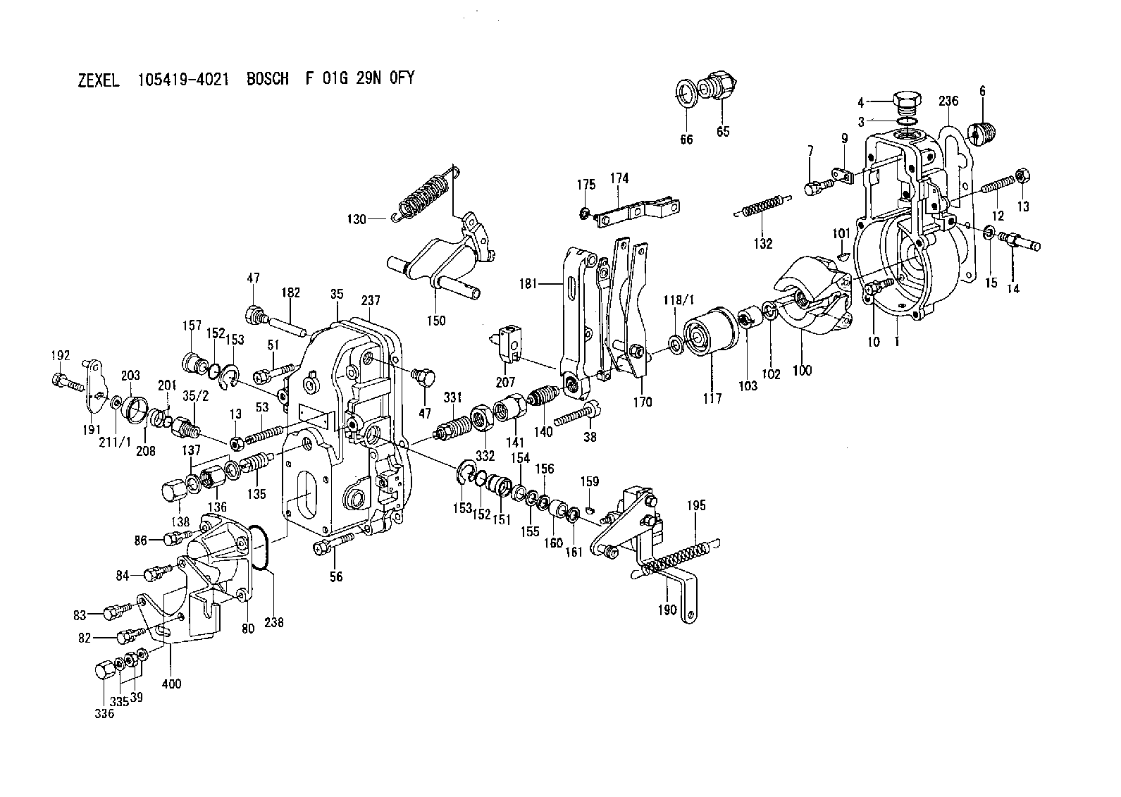
| 1. | [1] | 154000-6400 | GOVERNOR HOUSING |
| 3. | [1] | 029632-5070 | O-RING |
| 4. | [1] | 154007-2900 | CAPSULE |
| 6. | [1] | 154007-0200 | ADAPTOR |
| 7. | [1] | 020018-1840 | BLEEDER SCREW |
| 9. | [1] | 154350-1900 | PLATE |
| 10. | [6] | 029010-6810 | BLEEDER SCREW |
| 12. | [1] | 154010-0100 | FLAT-HEAD SCREW |
| 13. | [2] | 154011-0100 | HEXAGON NUT |
| 13. | [2] | 154011-0100 | HEXAGON NUT |
| 14. | [1] | 154013-2320 | BLEEDER SCREW |
| 15. | [1] | 014110-8440 | LOCKING WASHER D15.4&8.2T2 |
| 35. | [1] | 154500-1020 | GOVERNOR COVER |
| 35/2. | [1] | 154321-0400 | BUSHING |
| 38. | [1] | 154031-3000 | FLAT-HEAD SCREW |
| 39. | [1] | 139206-0600 | UNION NUT |
| 47. | [2] | 154036-0300 | CAPSULE |
| 47. | [2] | 154036-0300 | CAPSULE |
| 51. | [2] | 020106-5040 | BLEEDER SCREW |
| 53. | [1] | 154010-0200 | FLAT-HEAD SCREW |
| 56. | [4] | 020106-3840 | BLEEDER SCREW |
| 65. | [1] | 155404-5120 | STOPPING DEVICE |
| 66. | [1] | 026518-2240 | GASKET |
| 80. | [1] | 154063-5100 | COVER |
| 82. | [1] | 029020-6260 | BLEEDER SCREW |
| 83. | [1] | 029020-6260 | BLEEDER SCREW |
| 84. | [1] | 020006-2040 | BLEEDER SCREW |
| 86. | [1] | 020006-1640 | BLEEDER SCREW |
| 100. | [1] | 154101-0520 | FLYWEIGHT |
| 101. | [1] | 025803-1610 | WOODRUFF KEY 16 MM |
| 102. | [1] | 029321-2020 | LOCKING WASHER |
| 103. | [1] | 029231-2030 | UNION NUT |
| 117. | [1] | 154123-0120 | SLIDING PIECE |
| 118/1. | [0] | 029311-0010 | SHIM D14&10.1T0.2 |
| 118/1. | [0] | 029311-0180 | SHIM D14&10.1T0.3 |
| 118/1. | [0] | 029311-0190 | SHIM D14&10.1T0.40 |
| 118/1. | [0] | 029311-0210 | SHIM D14&10.1T1 |
| 118/1. | [0] | 139410-0000 | SHIM D14&10.1T0.5 |
| 118/1. | [0] | 139410-0100 | SHIM D14&10.1T1.5 |
| 118/1. | [0] | 139410-3000 | SHIM D14&10.1T2.0 |
| 118/1. | [0] | 139410-3100 | SHIM D14&10.1T3.0 |
| 118/1. | [0] | 139410-3200 | SHIM D14&10.1T4.0 |
| 130. | [1] | 154150-2700 | GOVERNOR SPRING |
| 132. | [1] | 154154-0500 | COILED SPRING |
| 135. | [1] | 154158-1020 | HEADLESS SCREW |
| 136. | [1] | 154011-1700 | UNION NUT |
| 137. | [2] | 026512-1540 | GASKET |
| 138. | [1] | 154159-1200 | CAP NUT |
| 140. | [1] | 154185-4420 | HEADLESS SCREW |
| 141. | [1] | 029201-6080 | UNION NUT |
| 150. | [1] | 154200-7220 | SWIVELLING LEVER |
| 151. | [1] | 154204-4300 | BUSHING |
| 152. | [2] | 029631-8020 | O-RING |
| 152. | [2] | 029631-8020 | O-RING |
| 153. | [2] | 016010-1640 | LOCKING WASHER |
| 153. | [2] | 016010-1640 | LOCKING WASHER |
| 154. | [1] | 139611-0000 | PACKING RING |
| 155. | [1] | 139411-0000 | SHIM |
| 156. | [0] | 029311-1070 | SHIM D16&11T0.5 |
| 157. | [1] | 154204-4400 | BUSHING |
| 159. | [1] | 025803-1310 | WOODRUFF KEY 13 MM |
| 160. | [1] | 154206-2800 | BUSHING |
| 161. | [0] | 154206-0200 | PLAIN WASHER D19.5&11.2T1.0 |
| 170. | [1] | 154216-3820 | FORK LEVER |
| 174. | [1] | 154230-3920 | STRAP |
| 175. | [1] | 016010-0540 | LOCKING WASHER |
| 181. | [1] | 154236-1500 | TENSIONING LEVER |
| 182. | [1] | 154237-0100 | BEARING PIN |
| 190. | [1] | 154395-9621 | CONTROL LEVER |
| 191. | [1] | 154382-6020 | CONTROL LEVER |
| 192. | [1] | 020006-1640 | BLEEDER SCREW |
| 195. | [1] | 154314-2600 | COILED SPRING |
| 201. | [1] | 029631-0030 | O-RING |
| 203. | [1] | 154322-0100 | CAP |
| 207. | [1] | 154326-5020 | CONTROL LEVER |
| 208. | [1] | 154327-7600 | COILED SPRING |
| 211/1. | [0] | 029311-0520 | SHIM D20.8&10.3T0.2 |
| 211/1. | [0] | 029311-0530 | SHIM D20.8&10.3T0.25 |
| 211/1. | [0] | 029311-0540 | SHIM D20.8&10.3T0.3 |
| 211/1. | [0] | 029311-0550 | SHIM D20.8&10.3T0.35 |
| 211/1. | [0] | 029311-0560 | SHIM D20.8&10.3T0.4 |
| 211/1. | [0] | 029311-0570 | SHIM D20.8&10.3T0.5 |
| 236. | [1] | 154390-0000 | GASKET |
| 237. | [1] | 154390-0300 | GASKET |
| 238. | [1] | 029635-2020 | O-RING |
| 331. | [1] | 154179-4720 | HEADLESS SCREW |
| 332. | [1] | 029201-6010 | UNION NUT |
| 335. | [2] | 026506-1040 | GASKET |
| 336. | [1] | 154035-1600 | CAP NUT |
| 400. | [1] | 154375-9600 | BRACKET |
Include in #1:
101482-9351
as GOVERNOR
Cross reference number
Zexel num
Bosch num
Firm num
Name
Information:
Gauges provide indications of engine performance. Be sure they are in good working order. You can determine what is the "normal" operating range by observing the gauges over a period of time.Noticeable changes in gauge readings indicate potential gauge or engine problems. This also applies to gauge readings that have changed significantly, but are still within specifications. The cause of any sudden or significant change in gauge readings should be determined and corrected. Contact your Caterpillar dealer for assistance as needed. Oil Pressure - Indicates engine oil pressure. The oil pressure should be greatest after starting a cold engine. Oil pressure should read between 240 and 480 kPa (35 and 70 psi) when: the engine is running between 600 and 2100 rpm with SAE 10W30 oil, at an operating oil temperature of 105°C (220°F). A lower pressure is normal at low idling speed.If the oil pressure gauge reading fluctuates after the load is stable:1. Remove the load.2. Reduce engine speed to low idle.3. Check and maintain the oil level.
Engine damage can result if the engine is operated with no oil pressure gauge reading. If no pressure is indicated, stop the engine.
Engine Oil Temperature - Indicates engine oil temperature. The purpose of the oil is to lubricate all moving parts inside the engine, and to cool the pistons and bearings. The oil cooler transfers the heat in the oil to the engine jacket water.If the cooling system cannot remove the necessary heat from the water, the engine oil cannot be properly cooled. Higher than normal oil temperature indicates a heat problem has occurred in the lubrication and/or cooling system, and a problem can occur with cylinder heads, liners, pistons or bearings. Maximum oil temperature is 110°C (230°F).Jacket Water Temperature - Indicates engine coolant temperature. It should normally indicate from 79 to 99°C (175 to 210°F). Higher temperatures may occur under certain conditions. Maximum allowable temperature is 105°C (220°F) with the cooling system pressurized.If the engine is operating above normal range and steam becomes apparent:1. Reduce the load and reduce the engine rpm.2. Inspect the engine for cooling system for leaks.3. Determine if the engine must be shutdown immediately or if the engine can be cooled by reducing the load. Inlet Air Temperature - Indicates inlet manifold air temperature. As the inlet air increases in temperature, the air expands, less oxygen is available in the cylinders, and less power is developed. As a result, at full speed position with a full load, the engine may be overloaded. Maximum inlet manifold air temperature is:* 110°C (230°F) for DITA engines* 163°C (325°F) for DIT engines Exhaust Stack Temperature - Indicates exhaust gas temperature. Maximum exhaust temperature is approximately 575°C (1065°F). Fuel Level - Indicates fuel level in the fuel tank. The electrically operated fuel level gauge registers only when the START/STOP (ignition) switch is ON. Fuel Pressure - Indicates fuel pressure to the injection pump. The indicator should register in the NORMAL (green) range.If the indicator moves to the OUT position or