Information
BOSCH
9 420 610 222
9420610222
ZEXEL
105410-5191
1054105191

Rating:
Scheme ###:
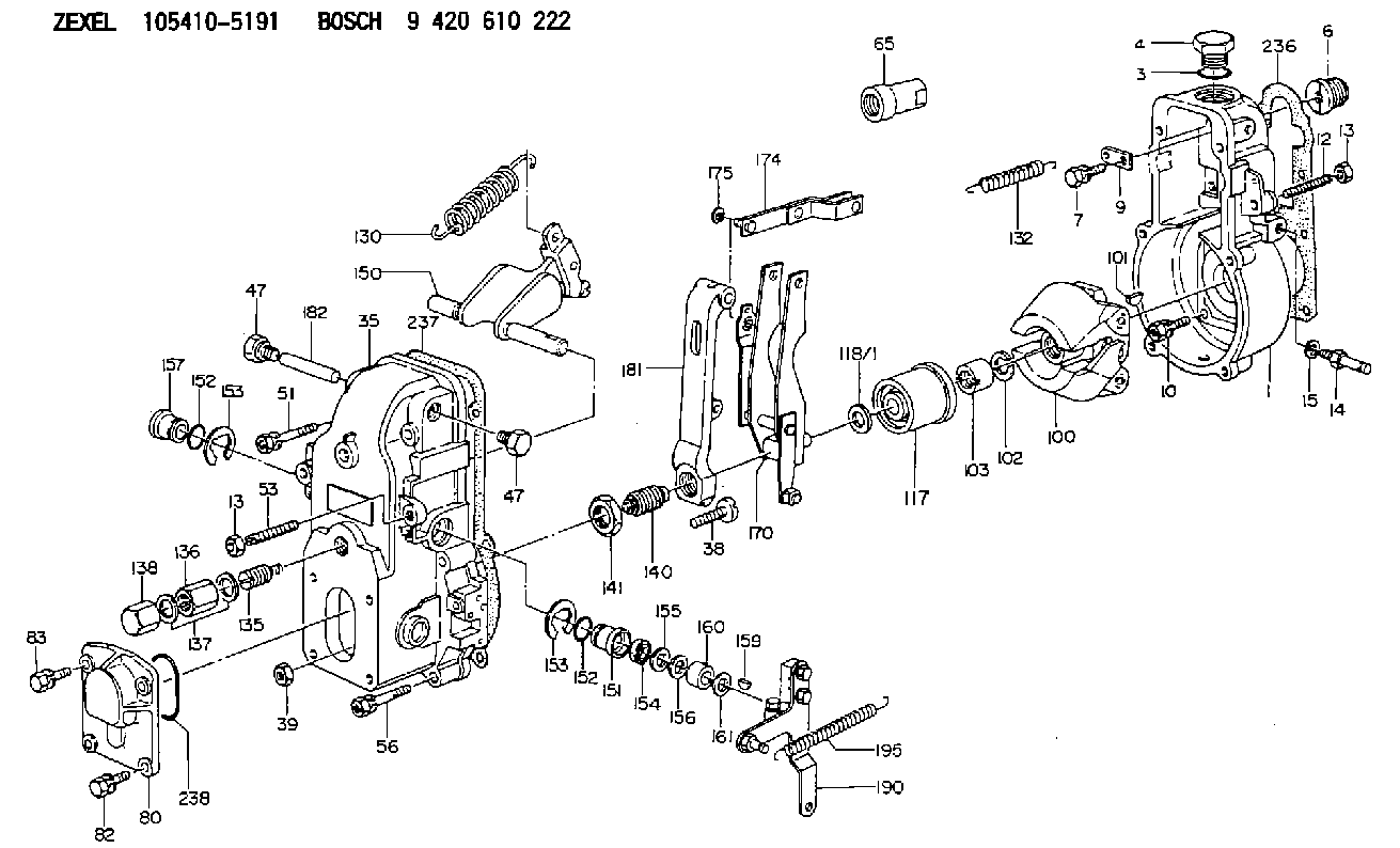
| 1. | [1] | 154000-6400 | GOVERNOR HOUSING |
| 3. | [1] | 029632-5070 | O-RING |
| 4. | [1] | 154007-2900 | CAPSULE |
| 6. | [1] | 154007-0200 | ADAPTOR |
| 7. | [1] | 020018-1840 | BLEEDER SCREW M8P1.25L18 |
| 9. | [1] | 154350-1900 | PLATE |
| 10. | [6] | 029010-6810 | BLEEDER SCREW |
| 12. | [1] | 154010-0100 | FLAT-HEAD SCREW |
| 13. | [2] | 154011-0100 | HEXAGON NUT |
| 13. | [2] | 154011-0100 | HEXAGON NUT |
| 14. | [1] | 154012-1500 | BLEEDER SCREW |
| 15. | [1] | 014110-8440 | LOCKING WASHER |
| 35. | [1] | 154500-2020 | GOVERNOR COVER |
| 38. | [1] | 154031-0100 | FLAT-HEAD SCREW |
| 39. | [1] | 013020-6020 | UNION NUT M6P1H5 |
| 47. | [2] | 154036-0300 | CAPSULE |
| 47. | [2] | 154036-0300 | CAPSULE |
| 51. | [2] | 020106-5040 | BLEEDER SCREW |
| 53. | [1] | 154010-0300 | FLAT-HEAD SCREW |
| 56. | [4] | 020106-3840 | BLEEDER SCREW |
| 65. | [1] | 155404-5300 | CAP |
| 80. | [1] | 154063-4600 | COVER |
| 82. | [2] | 029020-6210 | BLEEDER SCREW |
| 83. | [2] | 020006-1640 | BLEEDER SCREW M6P1L16 4T |
| 100. | [1] | 154100-3220 | FLYWEIGHT ASSEMBLY |
| 101. | [1] | 025803-1610 | WOODRUFF KEY |
| 102. | [1] | 029321-2020 | LOCKING WASHER |
| 103. | [1] | 029231-2030 | UNION NUT |
| 117. | [1] | 154123-0120 | SLIDING PIECE |
| 118/1. | [0] | 029311-0010 | SHIM D14&10.1T0.2 |
| 118/1. | [0] | 029311-0180 | SHIM D14&10.1T0.3 |
| 118/1. | [0] | 029311-0190 | SHIM D14&10.1T0.40 |
| 118/1. | [0] | 029311-0210 | SHIM D14&10.1T1 |
| 118/1. | [0] | 139410-0000 | SHIM D14.0&10.1T0.5 |
| 118/1. | [0] | 139410-0100 | SHIM D14.0&10.1T1.5 |
| 118/1. | [0] | 139410-3000 | SHIM D14&10.1T2.0 |
| 118/1. | [0] | 139410-3100 | SHIM D14&10.1T3.0 |
| 118/1. | [0] | 139410-3200 | SHIM D14&10.1T4.0 |
| 130. | [1] | 154150-0400 | GOVERNOR SPRING |
| 132. | [1] | 154154-0701 | COILED SPRING |
| 135. | [1] | 154157-0120 | HEADLESS SCREW |
| 136. | [1] | 029201-2030 | UNION NUT M12P1.0H4 |
| 137. | [2] | 026512-1540 | GASKET D15.4&12.2T1.50 |
| 138. | [1] | 154159-1200 | CAP NUT |
| 140. | [1] | 154177-0220 | HEADLESS SCREW |
| 141. | [1] | 029201-6010 | UNION NUT |
| 150. | [1] | 154200-6920 | SWIVELLING LEVER |
| 151. | [1] | 154204-3000 | BUSHING |
| 152. | [2] | 029631-8020 | O-RING |
| 152. | [2] | 029631-8020 | O-RING |
| 153. | [2] | 016010-1640 | LOCKING WASHER |
| 153. | [2] | 016010-1640 | LOCKING WASHER |
| 154. | [1] | 139611-0000 | PACKING RING |
| 155. | [1] | 139411-0000 | SHIM |
| 156. | [0] | 029311-1070 | SHIM D16&11T0.5 |
| 157. | [1] | 154204-3100 | BUSHING |
| 159. | [1] | 025803-1310 | WOODRUFF KEY |
| 160. | [1] | 154206-2800 | BUSHING |
| 161. | [0] | 154206-0200 | PLAIN WASHER D19.5&11.2T1.0 |
| 170. | [1] | 154211-3820 | FORK LEVER |
| 174. | [1] | 154230-0120 | STRAP |
| 175. | [1] | 016010-0540 | LOCKING WASHER |
| 181. | [1] | 154236-4100 | TENSIONING LEVER |
| 182. | [1] | 154237-0100 | BEARING PIN |
| 190. | [1] | 154342-1521 | CONTROL LEVER |
| 195. | [1] | 154314-0200 | COILED SPRING |
| 236. | [1] | 154390-0000 | GASKET |
| 237. | [1] | 154390-0300 | GASKET |
| 238. | [1] | 029635-2020 | O-RING |
Include in #1:
101452-9201
as GOVERNOR
Cross reference number
Zexel num
Bosch num
Firm num
Name
105410-5191
9 420 610 222
* K
Information:
1. Remove tachometer drive (3) from transfer pump cover (4).2. Remove bolts (1). Separate cover (4) and pump body (2). 3. Remove lip-type seal (6) from the cover. Remove plug (5), the seal, spring and plunger (bypass valve) from the cover. 4. Remove nut (10) from shaft (7). Remove gear (9) and key (11).5. Remove shaft (7) and gear (8) as a unit. Remove gear (8) from drive shaft (7) with a press.6. Remove idler gear (12). 7. Remove bushing (14), two lip-type seals and the bottom bearing from pump body (2).8. Remove check valve (13).Assemble Fuel Transfer Pump
1. Install bushing (4) in body (3) with Tooling (B). The bushing must be .80 .50 mm (.031 .020 in) below the (gear) surface of the body.2. Install the check valve in the body with Tooling (A).3. Install lip-type seal (5) with Tooling (C). Install the seal until it is 26.19 .13 mm (1.031 .005 in) from the bottom (drive gear) surface of body (3) and with the lip toward bushing (4) as shown.4. Install lip-type seal (6) with Tooling (D). Install the seal until it is 14.2 0.5 mm (.559 .020 in) from the bottom (drive gear) surface of body (3) and with the lip away from seal (5) as shown.5. Install bearing (7) in body (3) with Tooling (E). The bearing must be even with the bottom (drive gear) surface of the pump body. 6. Heat gear (8) to a maximum temperature of 315° C (600° F). Install gear (8) on shaft (11) until dimension (X) is 49.71 0.25 mm (1.957 .010 in).7. Install the drive shaft and gear in body (3). Install the key, gear (10) and nut (9). Tighten the nut to a torque of 30 7 N m (22 5 lb ft).8. Install idler gear (12) in body (3).9. Install lip-type seal (2) with Tooling (C). Install the seal until it is 22.61 .05 mm (.890 .002 in) from the top surface of cover (1) with the lip toward the inside as shown. 10. Install plunger (14) (bypass valve), spring (15) and seal and plug (13) in pump cover (1). Tighten plug (13) to a torque of 37 4 N m (27 3 lb ft).
Do not let the liquid gasket enter the pump during application or assembly.
11. Put 7M-7260 Liquid Gasket Material on the surface of cover (1). Install cover (1) on pump body (3). The drive shaft must turn freely after the bolts that hold the transfer pump together are tightened.12. Install the tachometer drive on cover (1).End By:a. install fuel transfer pump
Have questions with 105410-5191?
Group cross 105410-5191 ZEXEL
Isuzu
Isuzu
Ishikawajima-S
105410-5191
9 420 610 222