Information
BOSCH
F 01G 29N 0LH
f01g29n0lh
ZEXEL
105407-6681
1054076681

Rating:
Scheme ###:
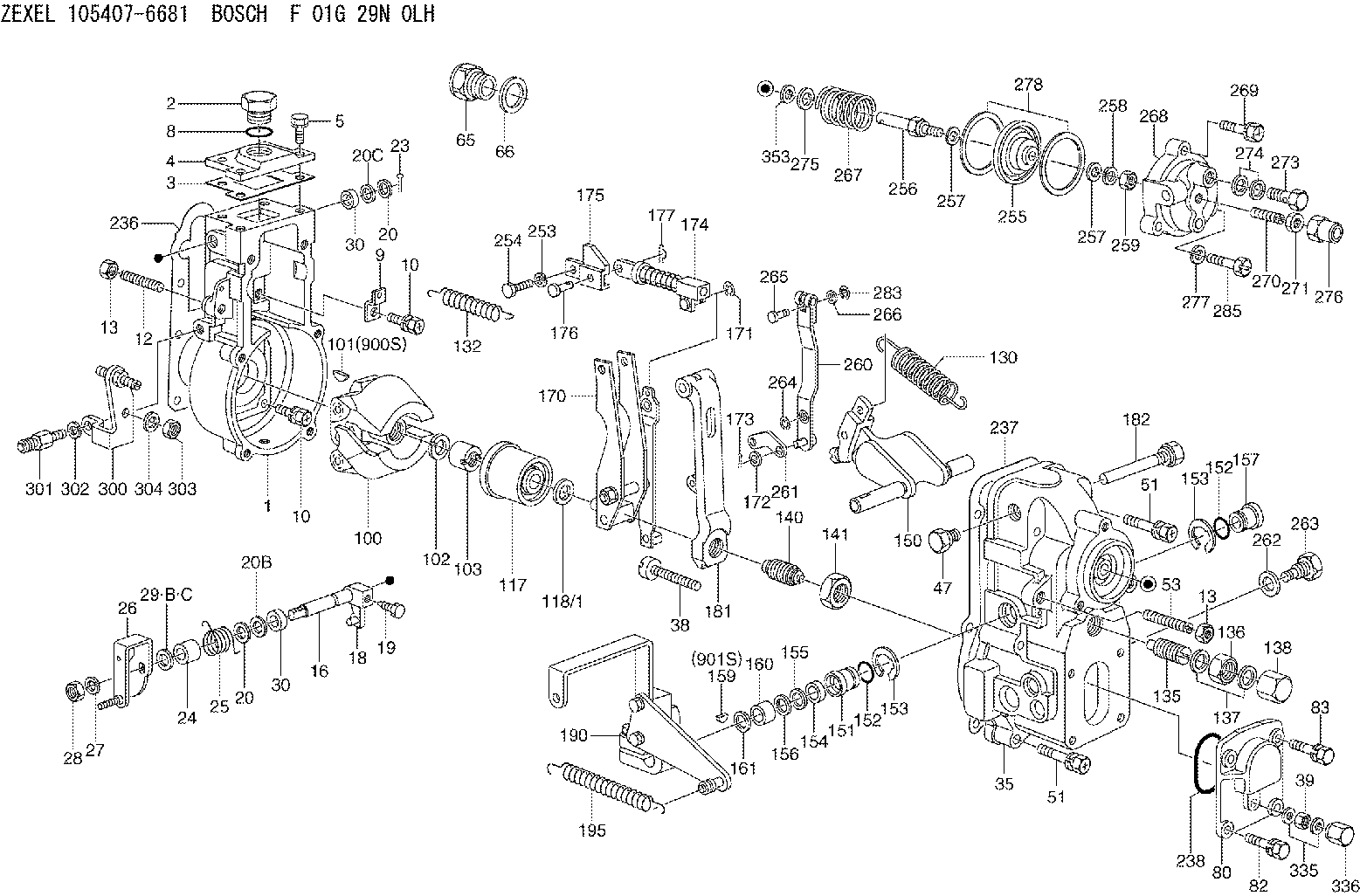
| 1. | [1] | 154004-2822 | GOVERNOR HOUSING |
| 2. | [1] | 154007-2900 | CAPSULE |
| 3. | [1] | 154358-2500 | SEAL RING |
| 4. | [1] | 154064-4500 | COVER |
| 5. | [4] | 020006-1640 | BLEEDER SCREW |
| 8. | [1] | 029632-5070 | O-RING |
| 9. | [1] | 154350-6000 | PLATE |
| 10. | [8] | 020106-2040 | BLEEDER SCREW |
| 10. | [8] | 020106-2040 | BLEEDER SCREW |
| 12. | [1] | 154010-1100 | FLAT-HEAD SCREW |
| 13. | [2] | 154011-0100 | HEXAGON NUT |
| 13. | [2] | 154011-0100 | HEXAGON NUT |
| 16. | [1] | 155004-3600 | LEVER SHAFT |
| 18. | [1] | 155003-2101 | CONTROL LEVER |
| 19. | [1] | 155006-0700 | BLEEDER SCREW |
| 20. | [1] | 139308-0900 | PLAIN WASHER D16&8T1 |
| 20. | [1] | 139308-0900 | PLAIN WASHER D16&8T1 |
| 20B. | [1] | 139308-1000 | PLAIN WASHER D16&8T1.5 |
| 20C. | [1] | 139408-1500 | SHIM D16&8T0.5 |
| 23. | [1] | 154373-2200 | SAFETY PIN |
| 24. | [1] | 154206-6300 | BUSHING |
| 25. | [1] | 154327-3600 | COILED SPRING |
| 26. | [1] | 154382-0720 | CONTROL LEVER |
| 27. | [1] | 014110-8440 | LOCKING WASHER D15.4&8.2T2 |
| 28. | [1] | 013020-8040 | UNION NUT |
| 29. | [1] | 139408-1500 | SHIM D16&8T0.5 |
| 29B. | [0] | 139408-1400 | SHIM D16&8T0.2 |
| 29C. | [0] | 139408-1500 | SHIM D16&8T0.5 |
| 29C. | [0] | 139408-1500 | SHIM D16&8T0.5 |
| 30. | [2] | 139608-0200 | PACKING RING |
| 30. | [2] | 139608-0200 | PACKING RING |
| 35. | [1] | 154022-6020 | GOVERNOR COVER |
| 38. | [1] | 154031-4800 | FLAT-HEAD SCREW |
| 39. | [1] | 139208-0400 | UNION NUT |
| 47. | [1] | 154036-0300 | CAPSULE |
| 51. | [6] | 020106-5040 | BLEEDER SCREW |
| 51. | [6] | 020106-5040 | BLEEDER SCREW |
| 53. | [1] | 154010-0200 | FLAT-HEAD SCREW |
| 65. | [1] | 155404-1700 | CAP |
| 66. | [1] | 026524-3040 | GASKET |
| 80. | [1] | 154063-7300 | COVER |
| 82. | [2] | 029020-6210 | BLEEDER SCREW |
| 83. | [2] | 020006-1640 | BLEEDER SCREW |
| 100. | [1] | 154101-0020 | FLYWEIGHT ASSEMBLY |
| 101. | [1] | 025803-1310 | WOODRUFF KEY 13 MM |
| 102. | [1] | 029321-2020 | LOCKING WASHER |
| 103. | [1] | 029231-2030 | UNION NUT |
| 117. | [1] | 154123-2320 | SLIDING PIECE |
| 118/1. | [0] | 029311-0010 | SHIM D14&10.1T0.2 |
| 118/1. | [0] | 029311-0180 | SHIM D14&10.1T0.3 |
| 118/1. | [0] | 029311-0190 | SHIM D14&10.1T0.40 |
| 118/1. | [0] | 029311-0210 | SHIM D14&10.1T1 |
| 118/1. | [0] | 139410-0000 | SHIM D14&10.1T0.5 |
| 118/1. | [0] | 139410-0100 | SHIM D14&10.1T1.5 |
| 118/1. | [0] | 139410-3000 | SHIM D14&10.1T2.0 |
| 118/1. | [0] | 139410-3100 | SHIM D14&10.1T3.0 |
| 118/1. | [0] | 139410-3200 | SHIM D14&10.1T4.0 |
| 130. | [1] | 154150-0400 | GOVERNOR SPRING |
| 132. | [1] | 154154-0500 | COILED SPRING |
| 135. | [1] | 154158-1720 | HEADLESS SCREW |
| 136. | [1] | 029201-2290 | UNION NUT |
| 137. | [2] | 026512-1540 | GASKET |
| 138. | [1] | 154159-1200 | CAP NUT |
| 140. | [1] | 154177-1620 | HEADLESS SCREW |
| 141. | [1] | 029201-6010 | UNION NUT |
| 150. | [1] | 154200-7020 | SWIVELLING LEVER |
| 151. | [1] | 154204-4300 | BUSHING |
| 152. | [2] | 139718-0200 | O-RING |
| 152. | [2] | 139718-0200 | O-RING |
| 153. | [2] | 016010-1640 | LOCKING WASHER |
| 153. | [2] | 016010-1640 | LOCKING WASHER |
| 154. | [1] | 139611-0300 | PACKING RING |
| 155. | [1] | 139411-0000 | SHIM |
| 156. | [0] | 029311-1070 | SHIM D16&11T0.5 |
| 157. | [1] | 154204-4400 | BUSHING |
| 159. | [1] | 025803-1310 | WOODRUFF KEY 13 MM |
| 160. | [1] | 154206-2800 | BUSHING |
| 161. | [0] | 154206-0200 | PLAIN WASHER D19.5&11.2T1.0 |
| 170. | [1] | 154217-2920 | FORK LEVER |
| 171. | [1] | 016010-0540 | LOCKING WASHER |
| 172. | [3] | 029310-5170 | SHIM |
| 173. | [2] | 025520-1210 | SPLIT PIN |
| 174. | [1] | 154235-5020 | STRAP |
| 175. | [1] | 154232-2420 | CONNECTOR |
| 176. | [1] | 159231-4900 | BEARING PIN |
| 177. | [1] | 155402-3800 | SAFETY PIN |
| 181. | [1] | 154236-4100 | TENSIONING LEVER |
| 182. | [1] | 154237-1100 | BEARING PIN |
| 190. | [1] | 154395-5520 | CONTROL LEVER |
| 195. | [1] | 154314-2600 | COILED SPRING |
| 236. | [1] | 154371-5600 | GASKET |
| 237. | [1] | 154390-0300 | GASKET |
| 238. | [1] | 029635-2020 | O-RING |
| 253. | [1] | 029320-5020 | LOCKING WASHER |
| 254. | [1] | 010535-1040 | FLAT-HEAD SCREW |
| 255. | [1] | 154400-7420 | DIAPHRAGM |
| 256. | [1] | 154400-4800 | STOP PIN |
| 257. | [2] | 029330-8050 | GASKET |
| 257. | [2] | 029330-8050 | GASKET |
| 258. | [1] | 139308-0700 | LOCKING WASHER |
| 259. | [1] | 013030-6040 | UNION NUT |
| 260. | [1] | 154401-3620 | CONTROL LEVER |
| 261. | [1] | 154401-1320 | STRAP |
| 262. | [1] | 026510-1440 | GASKET |
| 263. | [1] | 154401-2100 | BLEEDER SCREW |
| 264. | [1] | 016010-0540 | LOCKING WASHER |
| 265. | [1] | 154222-6200 | BEARING PIN |
| 266. | [1] | 029300-4010 | PLAIN WASHER |
| 267. | [1] | 154416-4100 | COILED SPRING |
| 268. | [1] | 154404-5000 | COVER |
| 269. | [2] | 020106-2540 | BLEEDER SCREW |
| 270. | [1] | 154034-1900 | FLAT-HEAD SCREW |
| 271. | [1] | 023040-6040 | UNION NUT |
| 273. | [1] | 029731-0180 | EYE BOLT |
| 274. | [2] | 026510-1340 | GASKET |
| 275. | [0] | 029312-0180 | SHIM D25.5&20T0.5 |
| 275B. | [0] | 029312-0210 | SHIM D25.5&20T0.2 |
| 276. | [1] | 154035-0320 | CAP NUT |
| 277. | [1] | 014110-6440 | LOCKING WASHER D12.2&6.1T1.5 |
| 278. | [2] | 154413-2600 | GASKET |
| 283. | [1] | 016010-0440 | LOCKING WASHER |
| 285. | [1] | 029010-6310 | BLEEDER SCREW |
| 300. | [1] | 154359-1320 | BRACKET |
| 301. | [1] | 154013-3420 | BLEEDER SCREW |
| 302. | [1] | 014110-8440 | LOCKING WASHER D15.4&8.2T2 |
| 303. | [1] | 154011-1100 | UNION NUT |
| 304. | [1] | 029300-8320 | SHIM |
| 335. | [2] | 026508-1140 | GASKET D11.4&8.2T1.0 |
| 336. | [1] | 154035-2000 | CAP NUT |
| 353. | [3] | 029310-9080 | SHIM |
| 900S. | [1] | 025803-1310 | WOODRUFF KEY 13 MM |
| 901S. | [1] | 025803-1610 | WOODRUFF KEY 16 MM |
Cross reference number
Zexel num
Bosch num
Firm num
Name
Information:
Removal of Lubrication System (1)
Removal of Lubrication System (2)
Disassembly Inspection and Reassembly Of Lubrication System
Oil Pump
Disassembly and Inspection of Oil Pump
Measurement of Clearance between Outer Rotor and Inner Rotor
Measure the clearance between the outer rotor and inner rotor, and, if the limit value is exceeded, replace the pump assembly.
Measurement of clearance between outer rotor and inner rotor Measurement of Rotor and Case End Play
Measure the rotor and case end play, and, if the limit value is exceeded, replace the pump assembly.
Measurement of rotor and case end play Measurement of Clearance Between Outer Rotor and Pump Case
Measure the clearance between the outer rotor and pump case, and, if the limit value is exceeded, replace the pump assembly.
Measure the clearance between the outer rotor and case Reassembly of Oil Pump
Install the outer rotor to the pump case, check alignment mark (indentation) on the pump case cover, and then tighten the bolts. If the alignment marks are not aligned during the reassembly, the pump will not suck oil.
Alignment marks on pump case and pump case coverOil Filter and Oil Cooler
Disassembly and Inspection of Oil Filter and Oil Cooler
Relief Valve
Inspection of Relief Valve
Relief Valve(1) Check the relief valve and valve seat for contact condition, and the spring for fatigue and damage, and replace any defective parts.(2) Measure the valve opening pressure (oil pressure when the engine is running at rated rpm) of the relief valve, and, if the standard valve is exceeded, remove the cap bolt and make an adjustment by increasing or decreasing the shim thickness.Engine oil pressure take-out port Next to oil filter - Rp 1/8 thread (PS 1/8) Installation of Lubrication System (1)
Installation of Lubrication System (2)