Information
BOSCH
F 01G 29N 0JS
f01g29n0js
ZEXEL
105400-7430
1054007430

Rating:
Scheme ###:
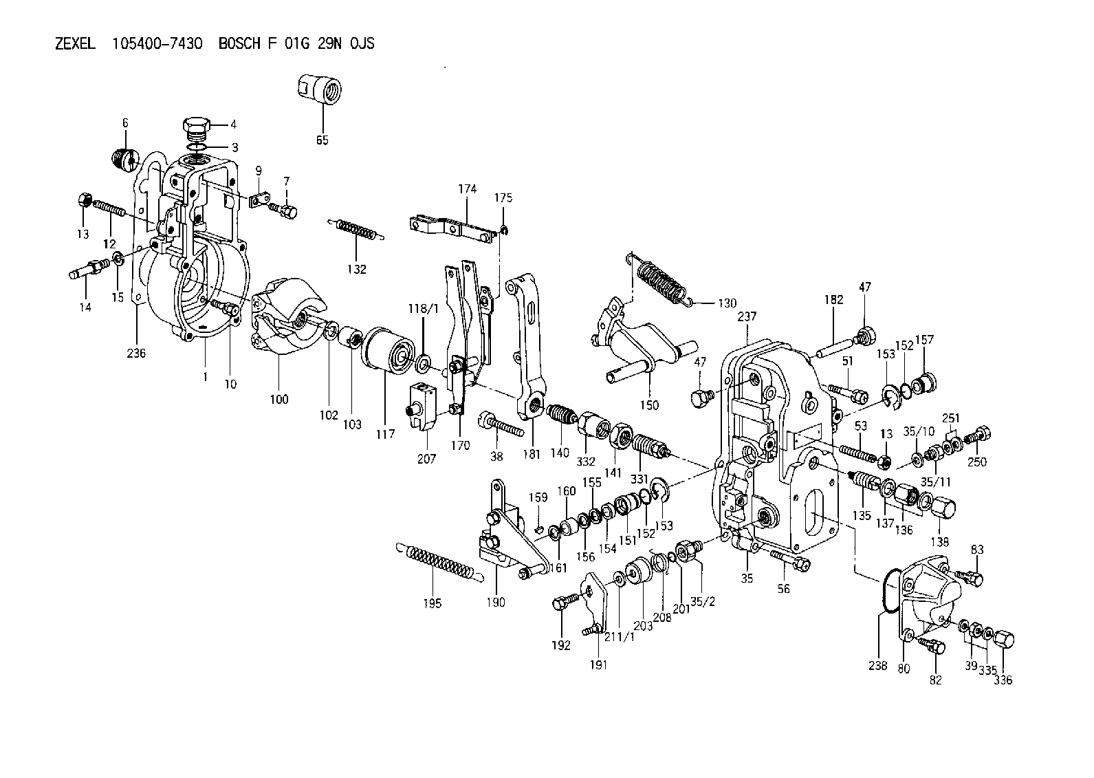
| 1. | [1] | 154000-6300 | GOVERNOR HOUSING |
| 3. | [1] | 029632-5070 | O-RING |
| 4. | [1] | 154007-2900 | CAPSULE |
| 6. | [1] | 154007-0200 | ADAPTOR |
| 7. | [1] | 020018-1840 | BLEEDER SCREW |
| 9. | [1] | 154350-1900 | PLATE |
| 10. | [6] | 029010-6810 | BLEEDER SCREW |
| 12. | [1] | 154010-0100 | FLAT-HEAD SCREW |
| 13. | [2] | 154011-0100 | HEXAGON NUT |
| 13. | [2] | 154011-0100 | HEXAGON NUT |
| 14. | [1] | 154012-2220 | BLEEDER SCREW |
| 15. | [1] | 014110-8440 | LOCKING WASHER D15.4&8.2T2 |
| 35. | [1] | 154500-8220 | GOVERNOR COVER |
| 35/2. | [1] | 154321-0400 | BUSHING |
| 35/10. | [1] | 026516-2040 | GASKET |
| 35/11. | [1] | 154316-6600 | ADAPTOR |
| 38. | [1] | 154031-3000 | FLAT-HEAD SCREW |
| 39. | [1] | 139206-0600 | UNION NUT |
| 47. | [2] | 154036-0300 | CAPSULE |
| 47. | [2] | 154036-0300 | CAPSULE |
| 51. | [2] | 020106-5040 | BLEEDER SCREW |
| 53. | [1] | 154010-0100 | FLAT-HEAD SCREW |
| 56. | [4] | 020106-3840 | BLEEDER SCREW |
| 65. | [1] | 154050-1720 | STOPPING DEVICE |
| 80. | [1] | 154063-5100 | COVER |
| 82. | [2] | 029020-6210 | BLEEDER SCREW |
| 83. | [2] | 020006-1640 | BLEEDER SCREW |
| 100. | [1] | 154101-0120 | FLYWEIGHT |
| 102. | [1] | 029321-2020 | LOCKING WASHER |
| 103. | [1] | 029231-2030 | UNION NUT |
| 117. | [1] | 154123-0120 | SLIDING PIECE |
| 118/1. | [0] | 029311-0010 | SHIM D14&10.1T0.2 |
| 118/1. | [0] | 029311-0180 | SHIM D14&10.1T0.3 |
| 118/1. | [0] | 029311-0190 | SHIM D14&10.1T0.40 |
| 118/1. | [0] | 029311-0210 | SHIM D14&10.1T1 |
| 118/1. | [0] | 139410-0000 | SHIM D14&10.1T0.5 |
| 118/1. | [0] | 139410-0100 | SHIM D14&10.1T1.5 |
| 118/1. | [0] | 139410-3000 | SHIM D14&10.1T2.0 |
| 118/1. | [0] | 139410-3100 | SHIM D14&10.1T3.0 |
| 118/1. | [0] | 139410-3200 | SHIM D14&10.1T4.0 |
| 130. | [1] | 154150-2700 | GOVERNOR SPRING |
| 132. | [1] | 154154-0701 | COILED SPRING |
| 135. | [1] | 154158-1320 | HEADLESS SCREW |
| 136. | [1] | 154011-1700 | UNION NUT |
| 137. | [2] | 026512-1540 | GASKET |
| 138. | [1] | 154159-1200 | CAP NUT |
| 140. | [1] | 154185-4120 | HEADLESS SCREW |
| 141. | [1] | 029201-6080 | UNION NUT |
| 150. | [1] | 154200-7120 | SWIVELLING LEVER |
| 151. | [1] | 154204-4300 | BUSHING |
| 152. | [2] | 029631-8020 | O-RING |
| 152. | [2] | 029631-8020 | O-RING |
| 153. | [2] | 016010-1640 | LOCKING WASHER |
| 153. | [2] | 016010-1640 | LOCKING WASHER |
| 154. | [1] | 139611-0000 | PACKING RING |
| 155. | [1] | 139411-0000 | SHIM |
| 156. | [0] | 029311-1070 | SHIM D16&11T0.5 |
| 157. | [1] | 154204-4400 | BUSHING |
| 159. | [1] | 025803-1310 | WOODRUFF KEY 13 MM |
| 160. | [1] | 154206-2800 | BUSHING |
| 161. | [0] | 154206-0200 | PLAIN WASHER D19.5&11.2T1.0 |
| 170. | [1] | 154210-0920 | FORK LEVER |
| 174. | [1] | 154230-3920 | STRAP |
| 175. | [1] | 016010-0540 | LOCKING WASHER |
| 181. | [1] | 154236-1500 | TENSIONING LEVER |
| 182. | [1] | 154237-0100 | BEARING PIN |
| 190. | [1] | 154343-1220 | CONTROL LEVER |
| 191. | [1] | 154366-8120 | CONTROL LEVER |
| 192. | [1] | 020006-1640 | BLEEDER SCREW |
| 195. | [1] | 154314-3600 | COILED SPRING |
| 201. | [1] | 029631-0030 | O-RING |
| 203. | [1] | 154322-0100 | CAP |
| 207. | [1] | 154326-5020 | CONTROL LEVER |
| 208. | [1] | 154327-7600 | COILED SPRING |
| 211/1. | [0] | 029311-0520 | SHIM D20.8&10.3T0.2 |
| 211/1. | [0] | 029311-0530 | SHIM D20.8&10.3T0.25 |
| 211/1. | [0] | 029311-0540 | SHIM D20.8&10.3T0.3 |
| 211/1. | [0] | 029311-0550 | SHIM D20.8&10.3T0.35 |
| 211/1. | [0] | 029311-0560 | SHIM D20.8&10.3T0.4 |
| 211/1. | [0] | 029311-0570 | SHIM D20.8&10.3T0.5 |
| 236. | [1] | 154390-0000 | GASKET |
| 237. | [1] | 154390-0300 | GASKET |
| 238. | [1] | 029635-2020 | O-RING |
| 250. | [1] | 029731-2040 | EYE BOLT |
| 251. | [2] | 029341-2140 | GASKET |
| 331. | [1] | 154172-3420 | HEADLESS SCREW |
| 332. | [1] | 029201-6010 | UNION NUT |
| 335. | [2] | 026506-1040 | GASKET |
| 336. | [1] | 154035-1600 | CAP NUT |
Include in #1:
101695-3570
as GOVERNOR
Cross reference number
Zexel num
Bosch num
Firm num
Name
Information:
To Remove Injection Nozzles
Special tooling is required. See the Service Manual for this engine or your Caterpillar dealer.Turbocharger, Jacket Water Pump and Raw Water Pump
Operation of the engine until the turbocharger fails, can cause severe damage to the turbocharger's compressor wheel and/or the engine. For example, damage to the turbocharger compressor wheel could cause parts from the compressor wheel to enter the engine cylinder and cause additional damage to the piston, valve and cylinder head.A failed water pump might cause severe engine overheating problems that could result in cracks in the cylinder head, a piston seizure or other potential damage to the engine.Inspect/Rebuild or Exchange Turbocharger
Turbocharger bearing failures can cause large quantities of oil to enter the air intake and exhaust systems. Loss of engine lubricant can result in serious engine damage.Minor leakage of a turbocharger housing under extended low idle operation will not cause problems as long as no turbocharger bearing failure occurred.When a turbocharger bearing failure is accompanied by a significant engine performance loss (exhaust smoke or engine speed up at no load), DO NOT continue engine operation until the turbocharger is repaired or replaced.
1. Remove the exhaust outlet piping and inlet piping from the turbocharger. Visually check for oil leaks.2. Turn the turbine and compressor wheel by hand.3. The assembly should turn freely.4. Inspect the turbine wheel and compressor wheel for contact with the turbocharger housing.5. There should NOT be any visible signs of contact between the turbine or compressor wheel and the turbocharger housing.Check the compressor wheel for cleanliness. If only the blade side of the wheel is dirty, dirt and/or moisture is passing through the air filtering system.If oil is found only on the back side of the wheel, it indicates a turbo oil seal leak. The leak may be the result of extended engine operation at low idle or an intake air line restriction (plugged filters).Maintain the compressor wheel/turbo housing by cleaning with standard shop solvents and a soft bristle brush.6. Check the end play and bearing clearance on the turbine wheel and shaft with a dial indicator. Attach the indicator and position the pointer on the end of turbocharger shaft. Push and pull on the other end of the shaft observing the dial indicator for total reading. End play should read between 0.076 to 0.203 mm (.003 to .008 inch). If indicator reading exceeds this tolerance, the turbocharger should be rebuilt or replaced. If indicator reading is less than 0.076 mm (.003 inch), it may be an indication of carbon build-up on the turbine wheel. The turbocharger should be disassembled, cleaned and inspected.If the measurements are not within specifications, the turbocharger must be repaired or replaced.7. When installing or replacing V-band clamps, position the gap (tightening screw) down if possible so any accumulation of moisture will drain away.Turbocharger components require precision clearances and balancing due to operation at high rotational (torsional) speeds. Severe Service Applications can accelerate component wear and may suggest the need to Inspect/Repair/Replace the cartridge at reduced intervals