Information
ZEXEL
104303-4040
1043034040

Rating:
Cross reference number
ZEXEL
104303-4040
1043034040
Zexel num
Bosch num
Firm num
Name
104303-4040
ISHIKAWAJIMA-S
H843 *
Calibration Data:
Adjustment conditions
Test oil
1404 Test oil ISO4113 or {SAEJ967d}
1404 Test oil ISO4113 or {SAEJ967d}
Test oil temperature
degC
40
40
45
Nozzle and nozzle holder
105780-8140
Bosch type code
EF8511/9A
Nozzle
105780-0000
Bosch type code
DN12SD12T
Nozzle holder
105780-2080
Bosch type code
EF8511/9
Opening pressure
MPa
17.2
Opening pressure
kgf/cm2
175
Injection pipe
Outer diameter - inner diameter - length (mm) mm 6-2-600
Outer diameter - inner diameter - length (mm) mm 6-2-600
Tester oil delivery pressure
kPa
157
157
157
Tester oil delivery pressure
kgf/cm2
1.6
1.6
1.6
Direction of rotation (viewed from drive side)
Right R
Right R
Injection timing adjustment
Direction of rotation (viewed from drive side)
Right R
Right R
Injection order
1-2-3
Pre-stroke
mm
1.95
1.9
2
Beginning of injection position
Drive side NO.1
Drive side NO.1
Difference between angles 1
Cyl.1-2 deg. 120 119.5 120.5
Cyl.1-2 deg. 120 119.5 120.5
Difference between angles 2
Cal 1-3 deg. 240 239.5 240.5
Cal 1-3 deg. 240 239.5 240.5
Injection quantity adjustment
Adjusting point
A
Rack position
9.5
Pump speed
r/min
875
875
875
Average injection quantity
mm3/st.
28
27
29
Max. variation between cylinders
%
0
-3
3
Basic
*
Fixing the lever
*
Injection quantity adjustment_02
Adjusting point
B
Rack position
7.9+-0.5
Pump speed
r/min
420
420
420
Average injection quantity
mm3/st.
8
7
9
Max. variation between cylinders
%
0
-14
14
Fixing the lever
*
Test data Ex:
Governor adjustment
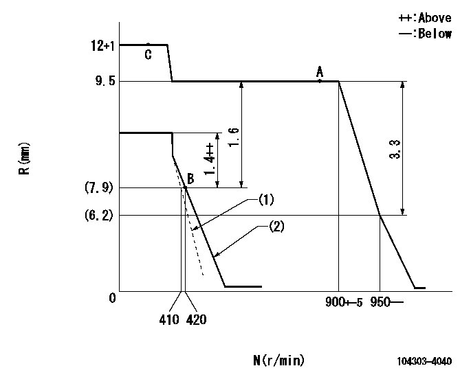
N:Pump speed
R:Rack position (mm)
(1)Main spring setting
(2)Set the idle spring.
----------
----------
----------
----------
Speed control lever angle

F:Full speed
I:Idle
----------
----------
a=15deg+-3deg b=30deg+-6deg
----------
----------
a=15deg+-3deg b=30deg+-6deg
Stop lever angle

N:Pump normal
S:Stop the pump.
----------
----------
a=(0deg) b=(38deg)
----------
----------
a=(0deg) b=(38deg)
Information:
Typical Example1. Turn the crankshaft until the "C" mark on the crankshaft gear is in alignment with the "C" mark on the camshaft gear. To keep the engine timing correct during removal and installation of the camshaft, put a mark on the teeth of the fuel injection pump drive gear and idler gear at location (A). Put a mark on the teeth of the idler gear and camshaft gear at location (B). When installing the camshaft, the engine timing will be correct when the marks at locations (A) and (B) are in alignment and the "C" marks on the crankshaft and camshaft gears are in alignment.2. Remove the bolts, lock and washer (1) that hold the camshaft in position.3. Remove the camshaft and gear (2). Do not cause damage to the lobes or bearings when the camshaft is removed.4. If necessary, remove the bolts and gear from the camshaft. The following steps are for the installation of the camshaft.5. Put the camshaft drive gear in position on the end of the camshaft, and install the bolts that hold it. Tighten the bolts to a torque of 55 7 N m (41 5 lb ft).
Do not cause damage to the lobes or bearings when the camshaft is installed.
6. Put 2P2506 Thread Lubricant on the camshaft lobes only, and clean engine oil on the bearing journals. Install camshaft (3) in the cylinder block, and make an alignment of the "C" marks and the marks put on the gears during removal.7. Install washer (1), the lock and bolts to hold the camshaft in position.End By:a. install valve liftersb. install timing gear cover
Have questions with 104303-4040?
Group cross 104303-4040 ZEXEL
Ishikawajima-S
Ishikawajima-S
104303-4040
H843