Information
BOSCH
F 01G 29M 03X
f01g29m03x
ZEXEL
102067-9060
1020679060

Rating:
Scheme ###:
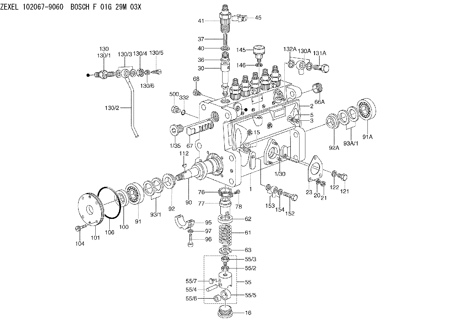
| 1. | [1] | 132050-1620 | PUMP HOUSING |
| 1/30. | [3] | 029040-6020 | STUD |
| 1/35. | [1] | 029112-4010 | CAPSULE |
| 2. | [1] | 132010-2520 | COVER |
| 3. | [3] | 132017-1100 | FLAT-HEAD SCREW |
| 5. | [3] | 026506-1040 | GASKET |
| 15. | [1] | 132030-1420 | LEVEL INDICATOR |
| 16. | [6] | 132034-0400 | CAPSULE |
| 20. | [3] | 014110-6440 | LOCKING WASHER D12.2&6.1T1.5 |
| 21. | [3] | 013020-6040 | UNION NUT |
| 23. | [1] | 132041-0600 | GASKET |
| 30. | [6] | 132101-4520 | PLUNGER-AND-BARREL ASSY 353NP6 |
| 36. | [6] | 140110-0820 | DELIVERY-VALVE ASSEMBLY 224P1 |
| 37. | [6] | 132112-0500 | COILED SPRING |
| 40. | [6] | 132115-0500 | GASKET |
| 41. | [6] | 132116-1300 | FITTING |
| 45. | [3] | 133122-1120 | PLATE |
| 55. | [6] | 132200-0520 | TAPPET |
| 55/2. | [6] | 132201-0100 | UNION NUT |
| 55/3. | [6] | 132202-0100 | HEXAGON SCREW |
| 55/4. | [6] | 132203-0200 | BEARING PIN |
| 55/5. | [6] | 132204-0300 | ROLLER |
| 55/6. | [6] | 132205-0200 | BUSHING |
| 55/7. | [6] | 132206-0100 | SLIDER |
| 61. | [6] | 132215-0300 | COMPRESSION SPRING |
| 62. | [6] | 140216-0300 | SLOTTED WASHER |
| 63. | [6] | 132217-0100 | SLOTTED WASHER |
| 66A. | [1] | 132222-0100 | BUSHING |
| 67. | [1] | 132256-0200 | CONTROL RACK |
| 68. | [1] | 132226-0400 | FLAT-HEAD SCREW |
| 76. | [6] | 132240-0200 | PINION |
| 77. | [6] | 132241-0200 | CONTROL SLEEVE |
| 78. | [6] | 131242-0100 | FLAT-HEAD SCREW |
| 90. | [1] | 132371-0000 | CAMSHAFT |
| 91. | [1] | 016650-2030 | BEARING PLATE |
| 91A. | [1] | 016650-2030 | BEARING PLATE |
| 92. | [1] | 132302-0300 | SPACER RING |
| 92A. | [1] | 132302-0300 | SPACER RING |
| 93/1. | [0] | 029312-6010 | SHIM D40&26T0.1 |
| 93/1. | [0] | 029312-6020 | SHIM D40&26T0.12 |
| 93/1. | [0] | 029312-6030 | SHIM D40&26T0.14 |
| 93/1. | [0] | 029312-6040 | SHIM D40&26T0.16 |
| 93/1. | [0] | 029312-6050 | SHIM D40&26T0.18 |
| 93/1. | [0] | 029312-6060 | SHIM D40&26T0.5 |
| 93A/1. | [0] | 029312-6010 | SHIM D40&26T0.1 |
| 93A/1. | [0] | 029312-6020 | SHIM D40&26T0.12 |
| 93A/1. | [0] | 029312-6030 | SHIM D40&26T0.14 |
| 93A/1. | [0] | 029312-6040 | SHIM D40&26T0.16 |
| 93A/1. | [0] | 029312-6050 | SHIM D40&26T0.18 |
| 93A/1. | [0] | 029312-6060 | SHIM D40&26T0.5 |
| 95. | [1] | 132305-0500 | BEARING SHELL |
| 96. | [2] | 029020-8140 | HEX-SOCKET-HEAD CAP SCREW |
| 97. | [2] | 026508-1240 | GASKET D11.9&8.2T1.0 |
| 100. | [1] | 026712-5010 | PACKING RING |
| 101. | [1] | 132316-3000 | COVER |
| 104. | [4] | 020006-1640 | BLEEDER SCREW |
| 106. | [1] | 029636-0030 | O-RING |
| 112. | [1] | 025805-1910 | WOODRUFF KEY |
| 121. | [1] | 133486-0200 | CAPSULE |
| 122. | [1] | 026510-1340 | GASKET |
| 130. | [1] | 132444-4020 | AIR FILTER |
| 130/1. | [1] | 132441-0200 | SPRING SEAT |
| 130/2. | [1] | 132442-4320 | PIPE |
| 130/3. | [2] | 026512-1540 | GASKET |
| 130/4. | [1] | 029241-2020 | UNION NUT |
| 130/5. | [1] | 132444-0300 | BLEEDER SCREW |
| 130/6. | [1] | 023010-8040 | UNION NUT |
| 130A. | [1] | 152308-1200 | INLET UNION |
| 131A. | [1] | 131601-3800 | BLEEDER SCREW |
| 132A. | [2] | 026514-1840 | GASKET |
| 145. | [1] | 155406-0220 | AIR FILTER |
| 146. | [1] | 026512-1640 | GASKET |
| 152. | [1] | 131601-4300 | EYE BOLT |
| 153. | [1] | 027110-0640 | INLET UNION |
| 154. | [2] | 026510-1440 | GASKET |
| 332. | [1] | 029638-4000 | O-RING |
| 500. | [1] | 029111-4100 | SCREW PLUG |
Cross reference number
Zexel num
Bosch num
Firm num
Name
Information:
General Information
Fig. 1-Fuel Pump LocationThe fuel transfer pump is located on the right side of the engine as shown on (1, Fig. 1).Removal
Disconnect and plug fuel lines (2, Fig. 1) at pump.Remove attaching hardware.Repair
Airtex Fuel Transfer Pumps
Fig. 2-Airtex Fuel Transfer PumpTo remove or install primer lever, (1, Fig. 2) compress rocker arm lever (2). And pull primer lever out.Further disassembly of the transfer pump is not possible.A.C. Fuel Transfer Pumps
When disassembling, mark pump cover and pump body for easier reassembly.Test all parts for serviceability and replace, if necessary.When assembling the fuel pump, observe the following:
Fig. 3-A.C. Fuel Transfer PumpMake sure diaphragm (1, Fig. 3) is engaged in rocker arm (2).Before installing the pump cover (3), position diaphragm so that it is level by moving rocker arm. Hold lever in this position.Install pump cover and cover screws. However, turn in screws so that they just contact the washers. Operate rocker arm several times, then release with a snap to make sure that diaphragm will not be overstretched when in use. Tighten cover screws in a crosswise pattern.Corona (B.C.D.) Fuel Transfer Pump
When disassembling, mark pump cover and pump body for easier reassembly.
Fig. 4-Diaphragm RemovalDisconnect diaphragm by pressing it against flange (Fig. 4).
Fig. 5-Remove Valve Plate and FilterCarefully remove valve plate with filter from pump cover (Fig. 5).Check all parts for serviceability and replace, if necessary.When assembling the fuel pump, observe the following: Make sure diaphragm is engaged in rocker arm.Before installing the pump cover, position diaphragm so that it is level by moving rocker arm. Hold lever in this position.Install pump cover and cover screws. However, turn in screws so that they just contact the washers.Operate rocker arm several times, then release with a snap to make sure that diaphragm will not be overstretched when in use.Tighten cover screws in a crosswise pattern.Installation
Using a new gasket, attach transfer pump to cylinder block. Connect lines and bleed fuel system.