Information
ZEXEL
101801-1910
1018011910
MITSUBISHI
3126173010
3126173010

Rating:
Service parts 101801-1910 INJECTION-PUMP ASSEMBLY:
1.
_
6.
COUPLING PLATE
7.
COUPLING PLATE
8.
_
9.
_
11.
Nozzle and Holder
31261-69050
12.
Open Pre:MPa(Kqf/cm2)
21.6{220}

15.
NOZZLE SET
Cross reference number
ZEXEL
101801-1910
1018011910
MITSUBISHI
3126173010
3126173010
Zexel num
Bosch num
Firm num
Name
Calibration Data:
Adjustment conditions
Test oil
1404 Test oil ISO4113 or {SAEJ967d}
1404 Test oil ISO4113 or {SAEJ967d}
Test oil temperature
degC
40
40
45
Nozzle
105015-3250
Bosch type code
DLLA160S354NP49
Nozzle holder
105030-4030
Opening pressure
MPa
21.6
Opening pressure
kgf/cm2
220
Injection pipe
Outer diameter - inner diameter - length (mm) mm 6-2-700
Outer diameter - inner diameter - length (mm) mm 6-2-700
Overflow valve
132424-0620
Overflow valve opening pressure
kPa
157
123
191
Overflow valve opening pressure
kgf/cm2
1.6
1.25
1.95
Tester oil delivery pressure
kPa
157
157
157
Tester oil delivery pressure
kgf/cm2
1.6
1.6
1.6
Direction of rotation (viewed from drive side)
Right R
Right R
Injection timing adjustment
Direction of rotation (viewed from drive side)
Right R
Right R
Injection order
1-2-7-3-
4-5-6-8
Pre-stroke
mm
4.5
4.45
4.55
Beginning of injection position
Governor side NO.1
Governor side NO.1
Difference between angles 1
Cyl.1-2 deg. 45 44.5 45.5
Cyl.1-2 deg. 45 44.5 45.5
Difference between angles 2
Cal 1-7 deg. 90 89.5 90.5
Cal 1-7 deg. 90 89.5 90.5
Difference between angles 3
Cal 1-3 deg. 135 134.5 135.5
Cal 1-3 deg. 135 134.5 135.5
Difference between angles 4
Cal 1-4 deg. 180 179.5 180.5
Cal 1-4 deg. 180 179.5 180.5
Difference between angles 5
Cal 1-5 deg. 225 224.5 225.5
Cal 1-5 deg. 225 224.5 225.5
Difference between angles 6
Cal 1-6 deg. 270 269.5 270.5
Cal 1-6 deg. 270 269.5 270.5
Difference between angles 7
Cal 1-8 deg. 315 314.5 315.5
Cal 1-8 deg. 315 314.5 315.5
Injection quantity adjustment
Adjusting point
A
Rack position
10.2
Pump speed
r/min
1200
1200
1200
Average injection quantity
mm3/st.
113
108.8
117.2
Max. variation between cylinders
%
0
-4
4
Fixing the lever
*
Injection quantity adjustment_02
Adjusting point
B
Rack position
10.2
Pump speed
r/min
800
800
800
Average injection quantity
mm3/st.
115
111.7
118.3
Max. variation between cylinders
%
0
-3
3
Basic
*
Fixing the lever
*
Injection quantity adjustment_03
Adjusting point
C
Rack position
8.2+-0.5
Pump speed
r/min
200
200
200
Average injection quantity
mm3/st.
17.5
14
21
Max. variation between cylinders
%
0
-15
15
Fixing the rack
*
Injection quantity adjustment_04
Adjusting point
D
Rack position
-
Pump speed
r/min
100
100
100
Average injection quantity
mm3/st.
144
144
Fixing the lever
*
Remarks
After startup boost setting
After startup boost setting
Timer adjustment
Pump speed
r/min
500+120-
100
Advance angle
deg.
0
0
0
Remarks
Start
Start
Timer adjustment_02
Pump speed
r/min
800
Advance angle
deg.
1.5
1
2
Timer adjustment_03
Pump speed
r/min
1000
Advance angle
deg.
3.2
2.7
3.7
Timer adjustment_04
Pump speed
r/min
1250
Advance angle
deg.
6.5
6.5
7.5
Remarks
Finish
Finish
Test data Ex:
Governor adjustment
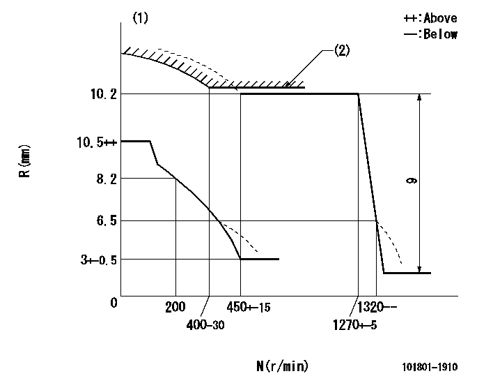
N:Pump speed
R:Rack position (mm)
(1)Beginning of damper spring operation: DL
(2)Set using excess fuel device for starting: SXL
----------
DL=5.5-0.2mm SXL=10.2+0.2mm
----------
----------
DL=5.5-0.2mm SXL=10.2+0.2mm
----------
0000000901
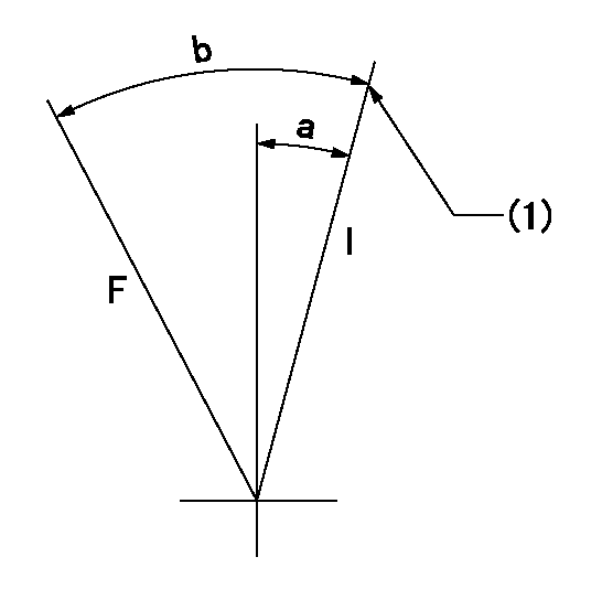
F:Full load
I:Idle
(1)Stopper bolt setting
----------
----------
a=5.5deg+-5deg b=26.5deg+-3deg
----------
----------
a=5.5deg+-5deg b=26.5deg+-3deg
0000001501 MICRO SWITCH
Adjustment of the micro-switch
Adjust the bolt to obtain the following lever position when the micro-switch is ON.
(1)Speed N1
(2)Rack position Ra
----------
N1=325+10r/min Ra=8.2mm
----------
----------
N1=325+10r/min Ra=8.2mm
----------
Information:
Introduction
The EPA has mandated that a DEF quality sensor must be installed on all engines built in 2017 or after. This new DEF quality sensor is integrated into the DEF header inside the DEF tank. The new style DEF header utilizes CAN C communication, so the wiring to the DEF header has been slightly modified on product going forward. However, the DCU remains compatible to both setups with the latest 507-7605 Engine Software. As part of the DEF quality sensor implementation, a new configuration parameter setting is used on the engine ECM in Cat® Electronic Technician (ET) to identify whether a DEF quality sensor is "installed" or "not installed". Below are some different fault codes for incompatible hardware and configuration setting as well as different service scenarios that may be encountered with this change and how to resolve any issues in these particular service scenarios. In addition to this Special Instruction, there is a video detailing these changes posted on Cat Channel 1.Channel1 Video
Note: A CWS login is required to access Caterpillar Channel1. Scan the QR code below with a QR enabled device or copy the link that follows.
Illustration 1 g06462430Reference: For more information, refer to "Diesel Exhaust Fluid Quality Sensor" on Caterpillar Channel1.https://channel1.mediaspace.kaltura.com/media/0_qyokrphe
Fault Codes When Parts/Settings Are Not Compatible
DEF quality header not installed but configuration set to installed.
Table 1
J1939 Code and Description CDL Code and Description
1235-9
J1939 Network #3 : Abnormal Update Rate 5856-9
J1939 Network #3 : Abnormal Update Rate DEF quality header installed but configuration set to not installed.
Table 2
J1939 Code and Description CDL Code and Description
1761-3
Aftertreatment 1 Diesel Exhaust Fluid Tank Level : Voltage Above Normal 3130-3
Aftertreatment #1 SCR Catalyst Reagent Tank #1 Level Sensor : Voltage Above Normal
3031-3
Aftertreatment 1 Diesel Exhaust Fluid Tank Temperature : Voltage Above Normal 3134-3
Aftertreatment #1 SCR Catalyst Reagent Tank #1 Temperature Sensor : Voltage Above Normal DEF Quality Sensor Service Scenarios
Listed below are the different examples of when the DEF Quality Sensor and associated components are needed.Replacement Industrial Engine (Built in 2016 or Before)
If these engines are replaced with an engine built in 2017 or after, the following updates will be required:
Updating to a DEF Quality Sensor by installing a new DEF Header
Wiring Harness
DCU Software
Change configuration status to "Installed" in Cat ETReplacement Machine Engine (Built in 2016 or Before)
If this engine is replaced with an engine built in 2016 or a previous Engine Arrangement Complete (EAC) engine, no other changes are needed.Confirm that the "DEF Quality Sensor" configuration is set to "Not Installed" in Cat ET.Replacement Machine Engine (Built in 2016 or Before)
If the engine is replaced with the latest EAC the following updates will be required:
Update to a DEF Quality Sensor by installing a new DEF header
Wiring harness
DCU Software
Change configuration status to "Installed" in Cat ETReplacement Engine (Built in 2017 or After)
Replace the engine with the latest EAC.Installing the DEF Quality Sensor on Engines Built in 2016 or Before
If installing the DEF Quality Sensor on engine built in 2016 or before, the following must be updated as well:
DCU software update
PETU