Information
ZEXEL
101801-1860
1018011860
MITSUBISHI
3126174010
3126174010

Rating:
Service parts 101801-1860 INJECTION-PUMP ASSEMBLY:
1.
_
7.
COUPLING PLATE
8.
_
9.
_
11.
Nozzle and Holder
31261-69050
12.
Open Pre:MPa(Kqf/cm2)
21.6{220}

15.
NOZZLE SET
Cross reference number
ZEXEL
101801-1860
1018011860
MITSUBISHI
3126174010
3126174010
Zexel num
Bosch num
Firm num
Name
Calibration Data:
Adjustment conditions
Test oil
1404 Test oil ISO4113 or {SAEJ967d}
1404 Test oil ISO4113 or {SAEJ967d}
Test oil temperature
degC
40
40
45
Nozzle
105015-3250
Bosch type code
DLLA160S354NP49
Nozzle holder
105030-4030
Opening pressure
MPa
21.6
Opening pressure
kgf/cm2
220
Injection pipe
Outer diameter - inner diameter - length (mm) mm 6-2-700
Outer diameter - inner diameter - length (mm) mm 6-2-700
Overflow valve
131424-1520
Overflow valve opening pressure
kPa
157
123
191
Overflow valve opening pressure
kgf/cm2
1.6
1.25
1.95
Tester oil delivery pressure
kPa
157
157
157
Tester oil delivery pressure
kgf/cm2
1.6
1.6
1.6
Direction of rotation (viewed from drive side)
Right R
Right R
Injection timing adjustment
Direction of rotation (viewed from drive side)
Right R
Right R
Injection order
1-2-7-3-
4-5-6-8
Pre-stroke
mm
4.5
4.45
4.55
Beginning of injection position
Governor side NO.1
Governor side NO.1
Difference between angles 1
Cyl.1-2 deg. 45 44.5 45.5
Cyl.1-2 deg. 45 44.5 45.5
Difference between angles 2
Cal 1-7 deg. 90 89.5 90.5
Cal 1-7 deg. 90 89.5 90.5
Difference between angles 3
Cal 1-3 deg. 135 134.5 135.5
Cal 1-3 deg. 135 134.5 135.5
Difference between angles 4
Cal 1-4 deg. 180 179.5 180.5
Cal 1-4 deg. 180 179.5 180.5
Difference between angles 5
Cal 1-5 deg. 225 224.5 225.5
Cal 1-5 deg. 225 224.5 225.5
Difference between angles 6
Cal 1-6 deg. 270 269.5 270.5
Cal 1-6 deg. 270 269.5 270.5
Difference between angles 7
Cal 1-8 deg. 315 314.5 315.5
Cal 1-8 deg. 315 314.5 315.5
Injection quantity adjustment
Adjusting point
A
Rack position
10.5
Pump speed
r/min
1200
1200
1200
Average injection quantity
mm3/st.
120
115.3
124.7
Max. variation between cylinders
%
0
-4
4
Fixing the lever
*
Injection quantity adjustment_02
Adjusting point
B
Rack position
10.5
Pump speed
r/min
800
800
800
Average injection quantity
mm3/st.
122
118.5
125.5
Max. variation between cylinders
%
0
-3
3
Basic
*
Fixing the lever
*
Injection quantity adjustment_03
Adjusting point
C
Rack position
8.2+-0.5
Pump speed
r/min
200
200
200
Average injection quantity
mm3/st.
17.5
14
21
Max. variation between cylinders
%
0
-15
15
Fixing the rack
*
Injection quantity adjustment_04
Adjusting point
D
Rack position
-
Pump speed
r/min
100
100
100
Average injection quantity
mm3/st.
144
144
Fixing the lever
*
Remarks
After startup boost setting
After startup boost setting
Timer adjustment
Pump speed
r/min
500+120-
100
Advance angle
deg.
0
0
0
Remarks
Start
Start
Timer adjustment_02
Pump speed
r/min
800
Advance angle
deg.
1.5
1
2
Timer adjustment_03
Pump speed
r/min
1000
Advance angle
deg.
3.2
2.7
3.7
Timer adjustment_04
Pump speed
r/min
1250
Advance angle
deg.
6.5
6.5
7.5
Remarks
Finish
Finish
Test data Ex:
Governor adjustment
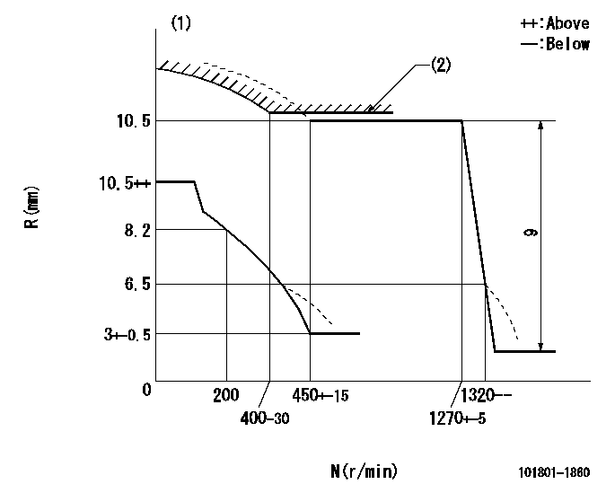
N:Pump speed
R:Rack position (mm)
(1)Beginning of damper spring operation: DL
(2)Set using excess fuel device for starting: SXL
----------
DL=5.5-0.2mm SXL=10.5+0.2mm
----------
----------
DL=5.5-0.2mm SXL=10.5+0.2mm
----------
0000000901
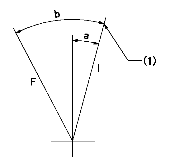
F:Full load
I:Idle
(1)Stopper bolt setting
----------
----------
a=5.5deg+-5deg b=27.5deg+-3deg
----------
----------
a=5.5deg+-5deg b=27.5deg+-3deg
0000001501 MICRO SWITCH
Adjustment of the micro-switch
Adjust the bolt to obtain the following lever position when the micro-switch is ON.
(1)Speed N1
(2)Rack position Ra
----------
N1=325+10r/min Ra=8.2mm
----------
----------
N1=325+10r/min Ra=8.2mm
----------
Information:
Introduction
The following Special Instruction must be used to package a DPF for a core return.
Wear goggles, gloves, protective clothing, and a National Institute for Occupational Safety and Health (NIOSH) approved P95 or N95 half-face respirator when handling a used Diesel Particulate Filter or Catalytic Converter Muffler. Failure to do so could result in personal injury.
Note: Whenever the filter is replaced the engine ash model must be reset. Refer to the section below for information on how to reset the ash model.Reset the Engine Ash Model
The engine ash model must be reset whenever the filter is cleaned or replaced. Reseting the ash model places the DPF volume back to the "Clean State". The resetting will allow the regeneration of the DPF to function properly.
Use Cat ET to access the configuration parameters. Select "Service" from the top menu then select "Service Procedures" then select "DPF Ash Service" from the menu in the service tool.
Choose the correct replacement type of diesel particulate filter in the menu that appears. The types of replacements for the diesel particulate filter are the following:
"Field cleaned" A DPF that has been cleaned and reapplied.
"New" A new DPF replacement.
"Remanufactured" A remanufactured DPF replacement.
Once the reset is completed, a log of the reset is captured and visible as a new row of information in the "DPF Ash Service" screen. Resetting the engine ash model does not reset the soot level.
Perform a "Manual DPF Regeneration" with Cat® ET to reset the soot levelPackaging Instructions
Note: The replacement DPF will be packaged with a bag and zip-tie that are used to repackage the DPF that has been removed.
Place the DPF being returned in the enclosed bag and seal the bag with the enclosed zip-tie.
Place the enclosed warning label on the outside of the bag.
Place half of the foam insert on the bottom of the original shipping box with the cut out in the insert facing up.
Place the DPF into the box fitting the DPF into the cut out in the insert.
Place the second half of the foam insert on to of the DPF with the cut out in the insert facing down onto the DPF.
Seal the box with packing tape.Note: If the package weighs over 16 kg (35 lb), additional tape or banding might be required.
Label the package for return shipment.