Information
ZEXEL
101681-9580
1016819580

Rating:
Service parts 101681-9580 INJECTION-PUMP ASSEMBLY:
1.
_

6.
COUPLING PLATE
7.
COUPLING PLATE
8.
_
9.
_
11.
Nozzle and Holder
12.
Open Pre:MPa(Kqf/cm2)
18.1{185}

15.
NOZZLE SET
Include in #1:
101681-9580
as INJECTION-PUMP ASSEMBLY
Cross reference number
ZEXEL
101681-9580
1016819580
Zexel num
Bosch num
Firm num
Name
101681-9580
Calibration Data:
Adjustment conditions
Test oil
1404 Test oil ISO4113 or {SAEJ967d}
1404 Test oil ISO4113 or {SAEJ967d}
Test oil temperature
degC
40
40
45
Nozzle and nozzle holder
105780-8140
Bosch type code
EF8511/9A
Nozzle
105780-0000
Bosch type code
DN12SD12T
Nozzle holder
105780-2080
Bosch type code
EF8511/9
Opening pressure
MPa
17.2
Opening pressure
kgf/cm2
175
Injection pipe
Outer diameter - inner diameter - length (mm) mm 6-2-600
Outer diameter - inner diameter - length (mm) mm 6-2-600
Overflow valve opening pressure
kPa
157
123
191
Overflow valve opening pressure
kgf/cm2
1.6
1.25
1.95
Tester oil delivery pressure
kPa
157
157
157
Tester oil delivery pressure
kgf/cm2
1.6
1.6
1.6
Direction of rotation (viewed from drive side)
Right R
Right R
Injection timing adjustment
Direction of rotation (viewed from drive side)
Right R
Right R
Injection order
1-5-3-6-
2-4
Pre-stroke
mm
2.2
2.15
2.25
Beginning of injection position
Drive side NO.1
Drive side NO.1
Difference between angles 1
Cal 1-5 deg. 60 59.5 60.5
Cal 1-5 deg. 60 59.5 60.5
Difference between angles 2
Cal 1-3 deg. 120 119.5 120.5
Cal 1-3 deg. 120 119.5 120.5
Difference between angles 3
Cal 1-6 deg. 180 179.5 180.5
Cal 1-6 deg. 180 179.5 180.5
Difference between angles 4
Cyl.1-2 deg. 240 239.5 240.5
Cyl.1-2 deg. 240 239.5 240.5
Difference between angles 5
Cal 1-4 deg. 300 299.5 300.5
Cal 1-4 deg. 300 299.5 300.5
Injection quantity adjustment
Adjusting point
A
Rack position
9.7
Pump speed
r/min
1100
1100
1100
Average injection quantity
mm3/st.
46
44.8
47.2
Max. variation between cylinders
%
0
-2.5
2.5
Basic
*
Fixing the lever
*
Injection quantity adjustment_02
Adjusting point
B
Rack position
10
Pump speed
r/min
800
800
800
Average injection quantity
mm3/st.
42
38.6
45.4
Fixing the lever
*
Injection quantity adjustment_03
Adjusting point
C
Rack position
7.7+-0.5
Pump speed
r/min
300
300
300
Average injection quantity
mm3/st.
9.4
8.1
10.7
Max. variation between cylinders
%
0
-14
14
Fixing the rack
*
Injection quantity adjustment_04
Adjusting point
D
Rack position
-
Pump speed
r/min
100
100
100
Average injection quantity
mm3/st.
65
55
75
Fixing the lever
*
Remarks
Startup boost setting
Startup boost setting
Timer adjustment
Pump speed
r/min
550--
Advance angle
deg.
0
0
0
Remarks
Start
Start
Timer adjustment_02
Pump speed
r/min
500
Advance angle
deg.
0.5
Timer adjustment_03
Pump speed
r/min
700
Advance angle
deg.
1
0.5
1.5
Timer adjustment_04
Pump speed
r/min
1100
Advance angle
deg.
2.7
2
3.4
Timer adjustment_05
Pump speed
r/min
1400
Advance angle
deg.
4.4
3.7
5.1
Timer adjustment_06
Pump speed
r/min
1500
Advance angle
deg.
4.8
4.1
5.5
Timer adjustment_07
Pump speed
r/min
-
Advance angle
deg.
6
6
6
Remarks
Measure the actual speed, stop
Measure the actual speed, stop
Test data Ex:
Governor adjustment
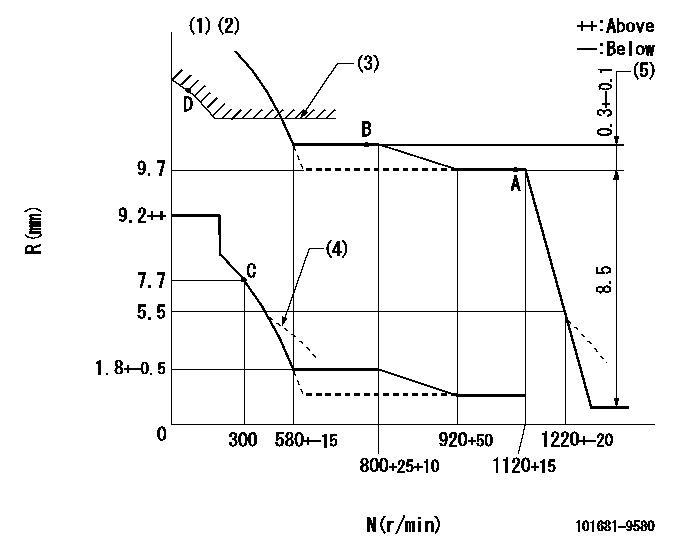
N:Pump speed
R:Rack position (mm)
(1)Lever ratio: RT
(2)Target shim dimension: TH
(3)Excess fuel setting for starting: SXL
(4)Damper spring setting: DL
(5)Rack difference between N = N1 and N = N2
----------
RT=1 TH=2.3mm SXL=10.1+0.2mm DL=5.2-0.2mm N1=1100r/min N2=800r/min
----------
----------
RT=1 TH=2.3mm SXL=10.1+0.2mm DL=5.2-0.2mm N1=1100r/min N2=800r/min
----------
Speed control lever angle

F:Full speed
----------
----------
a=0deg+-5deg
----------
----------
a=0deg+-5deg
0000000901
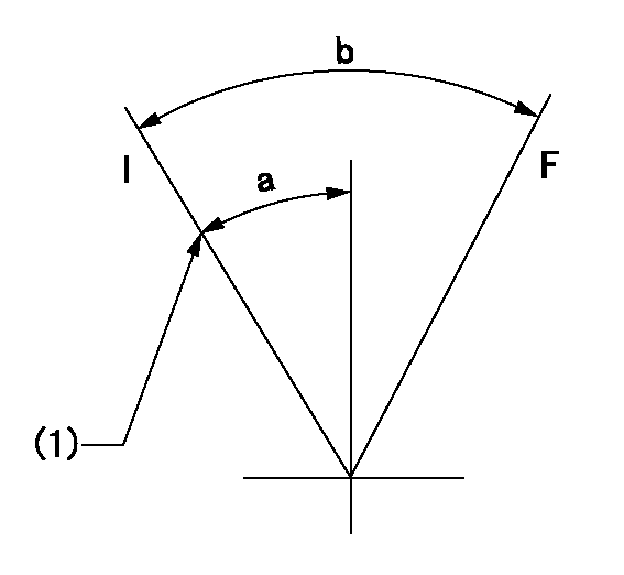
F:Full load
I:Idle
(1)Stopper bolt setting
----------
----------
a=16deg+-5deg b=30deg+-3deg
----------
----------
a=16deg+-5deg b=30deg+-3deg
Stop lever angle

N:Pump normal
S:Stop the pump.
----------
----------
a=20deg+-5deg b=71deg+-5deg
----------
----------
a=20deg+-5deg b=71deg+-5deg
Timing setting

(1)Pump vertical direction
(2)Position of gear's standard installation threaded hole at No 1 cylinder's beginning of injection
(3)-
(4)-
----------
----------
a=(50deg)
----------
----------
a=(50deg)
Information:
Safety is basically common sense. There are standard safety rules but each situation has its own peculiarities which cannot always be covered by rules. Your experience and common sense will be your best guide to safety. Be ever watchful for safety hazards and correct deficiencies promptly.Use the following safety precautions as a general guide to safe driving and maintenance practice. It is your responsibility to practice and promote safety. 1. Obey the rules of the road.2. Never adjust or repair engine or vehicle while it is in operation.3. Remove all tools and electrical cords before starting engine or operating vehicle.4. Keep work area clean.5. Store oily rags in containers.6. Store flammable liquids in a safe place away from the work area.7. Do not smoke around batteries. Hydrogen gas generated by charging is explosive. Keep batteries in a well ventilated area.8. Observe NO SMOKING signs.9. Do not wear loose clothing.10. Never operate an engine except in a well ventilated area.11. Do not exceed 30 PSI (2 kg/cm2) of air pressure when cleaning with air. Servicing cab-over truck engines require additional safety precautions as follows: Before Tilting Cab:1. Check clearance above and in front of truck cab.2. Keep tool chests and workbenches away from front of cab.3. Inspect sleeper and cab interior for loose luggage, tools and liquid containers which could fall forward.4. Check "Buddy" or "Jump" seats on right side of cab to be sure they are secured in place. While Tilting Cab1. Be sure the governor, transmission and clutch linkage do not interfere with the cab.2. Check position of steering shaft U-joint to prevent binding.
BEFORE TILTING CAB CHECK AREA FOR SUFFICIENT CLEARANCE AND OBSTRUCTIONS3. Never work under a partially tilted cab, unless it is properly secured.4. When cab is tilted past the over-center position, use cables or chains to prevent the cab from falling beyond the over-center point. Do not rely on cab hydraulic lift mechanism to retain or break the fall of the cab. While Cab is Tilted1. If it is necessary to open a door, take care to avoid damage to door hinges and/or window glass. While Lowering Cab1. Watch all governor, steering, clutch and transmission linkage. Bellcranks may turn over center, shift levers jam against bottom of cab and some models of clutch links separate when tilting cab. These clutch linkage components can miss their mating part when the cab is lowered.2. Be sure mating ends of exhaust and air cleaner inlet pipes align properly.3. Be sure cab lowers properly on mounting and locating pins. Twisted or misaligned cabs may miss locating pins and cab latch will not secure cab in locked position.4. Lock cab latching mechanism when cab is all the way down.
BEFORE TILTING CAB CHECK AREA FOR SUFFICIENT CLEARANCE AND OBSTRUCTIONS3. Never work under a partially tilted cab, unless it is properly secured.4. When cab is tilted past the over-center position, use cables or chains to prevent the cab from falling beyond the over-center point. Do not rely on cab hydraulic lift mechanism to retain or break the fall of the cab. While Cab is Tilted1. If it is necessary to open a door, take care to avoid damage to door hinges and/or window glass. While Lowering Cab1. Watch all governor, steering, clutch and transmission linkage. Bellcranks may turn over center, shift levers jam against bottom of cab and some models of clutch links separate when tilting cab. These clutch linkage components can miss their mating part when the cab is lowered.2. Be sure mating ends of exhaust and air cleaner inlet pipes align properly.3. Be sure cab lowers properly on mounting and locating pins. Twisted or misaligned cabs may miss locating pins and cab latch will not secure cab in locked position.4. Lock cab latching mechanism when cab is all the way down.
Have questions with 101681-9580?
Group cross 101681-9580 ZEXEL
Nissan-Diesel
101681-9580