Information
ZEXEL
101492-3300
1014923300
KOMATSU
6130721310
6130721310

Rating:
Service parts 101492-3300 INJECTION-PUMP ASSEMBLY:
1.
_
3.
GOVERNOR
5.
AUTOM. ADVANCE MECHANIS
6.
COUPLING PLATE
8.
_
9.
_
11.
Nozzle and Holder
6130-12-3100
12.
Open Pre:MPa(Kqf/cm2)
22.1{225}
15.
NOZZLE SET
Cross reference number
ZEXEL
101492-3300
1014923300
KOMATSU
6130721310
6130721310
Zexel num
Bosch num
Firm num
Name
Calibration Data:
Adjustment conditions
Test oil
1404 Test oil ISO4113 or {SAEJ967d}
1404 Test oil ISO4113 or {SAEJ967d}
Test oil temperature
degC
40
40
45
Nozzle and nozzle holder
105780-8140
Bosch type code
EF8511/9A
Nozzle
105780-0000
Bosch type code
DN12SD12T
Nozzle holder
105780-2080
Bosch type code
EF8511/9
Opening pressure
MPa
17.2
Opening pressure
kgf/cm2
175
Injection pipe
Outer diameter - inner diameter - length (mm) mm 6-2-600
Outer diameter - inner diameter - length (mm) mm 6-2-600
Overflow valve
132424-0620
Overflow valve opening pressure
kPa
157
123
191
Overflow valve opening pressure
kgf/cm2
1.6
1.25
1.95
Tester oil delivery pressure
kPa
157
157
157
Tester oil delivery pressure
kgf/cm2
1.6
1.6
1.6
Direction of rotation (viewed from drive side)
Right R
Right R
Injection timing adjustment
Direction of rotation (viewed from drive side)
Right R
Right R
Injection order
1-2-4-3
Pre-stroke
mm
3
2.95
3.05
Beginning of injection position
Governor side NO.1
Governor side NO.1
Difference between angles 1
Cyl.1-2 deg. 90 89.5 90.5
Cyl.1-2 deg. 90 89.5 90.5
Difference between angles 2
Cal 1-4 deg. 180 179.5 180.5
Cal 1-4 deg. 180 179.5 180.5
Difference between angles 3
Cal 1-3 deg. 270 269.5 270.5
Cal 1-3 deg. 270 269.5 270.5
Injection quantity adjustment
Adjusting point
B
Rack position
9.1
Pump speed
r/min
1200
1200
1200
Average injection quantity
mm3/st.
55.5
53.5
57.5
Max. variation between cylinders
%
0
-2
2
Basic
*
Fixing the rack
*
Injection quantity adjustment_02
Adjusting point
C
Rack position
8.1
Pump speed
r/min
375
375
375
Average injection quantity
mm3/st.
14
12.6
15.4
Max. variation between cylinders
%
0
-10
10
Fixing the rack
*
Test data Ex:
Governor adjustment
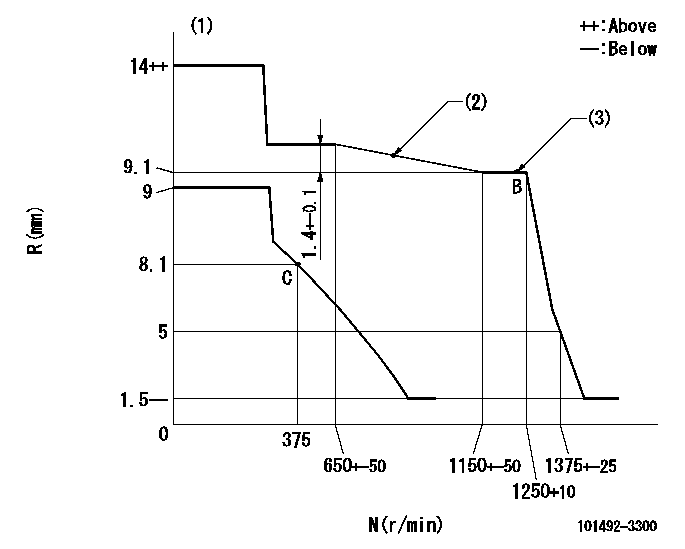
N:Pump speed
R:Rack position (mm)
(1)Target notch: K
(2)Adjust the torque control so that the rack position is R1 at speed N1.
(3)Supplied with torque spring not set.
----------
K=9 R1=10.1+-0.1mm N1=800r/min
----------
----------
K=9 R1=10.1+-0.1mm N1=800r/min
----------
Speed control lever angle

F:Full speed
I:Idle
S:Stop
----------
----------
a=13deg+-5deg b=32deg+-3deg c=32deg+-5deg
----------
----------
a=13deg+-5deg b=32deg+-3deg c=32deg+-5deg
0000001501 LEVER
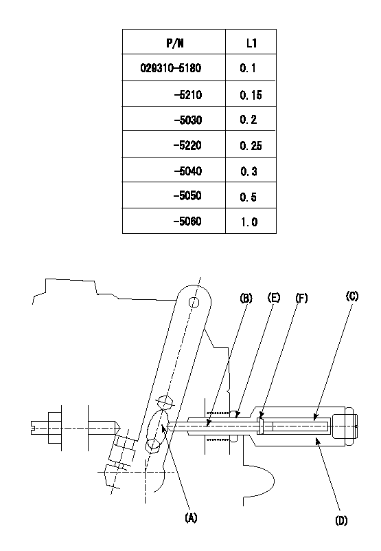
(F) P/N: Part number of the shim
L1:Thickness (mm)
1. Adjustment of the control lever
(1)Perform idling with the control lever (A) contacting the pushrod (B). At this time, confirm that the spring (C) is not compressed by control lever (A)'s operating torque.
(2)To set the stop position, compress spring (C) using the control lever (A) and adjust the rack so that it contacts the guide screw (D) at position L2. Then, set and fix using the lock nut (E). Adjust the rack position L2 at this time using the shim (F).
(3)Confirm that the control lever (A) returns to the idling position when pulled in the stop direction and then released.
----------
L2=0.2~2mm
----------
----------
L2=0.2~2mm
----------
Information:
To prevent possible personal injury, care must be taken when pin (17) is removed. The spring and plunger behind pin (17) are under spring force.
11. Remove pin (17), the spring and the plunger from the control lever.12. Remove band assembly (18) from the lever assembly. 13. Remove two seals (20) and bearing (19) from the governor housing. 14. Remove spring (22) from governor bolt (21).15. Remove seat (23) from riser (24).16. Remove the dowel from riser (24).17. Remove riser (24) and governor bolt (21) as a unit from governor plate (25).18. Remove governor bolt (21) from riser (24). 19. Remove spring (27) and washer (26) from the sleeve.20. Remove sleeve (28) from the servo piston valve. 21. Remove ring (32), large race (31), bearing (29) and small race (30) from sleeve (28). 22. Remove lock (34) from flyweights (33).23. Remove flyweight (33) from the governor plate. 24. Turn the governor plate over, and bend locks (36) down. Remove bolts (37), bracket (35) and the servo piston assembly from the governor plate. 25. Remove dowel (43), lever (44) and the servo piston assembly from bracket (35).26. Remove pin (42) and piston (38) from sleeve (40).27. Remove valve (39) from piston (38).28. Remove O-ring seal (41) from sleeve (40). 29. Tap lightly on cylinder (45) to remove it from the governor plate. 30. Remove O-ring seals (46) from cylinder (45). 31. Use Tool (A) to remove retaining ring (47) from the gear assembly. 32. Remove ring (51), spring (50), drive assembly (48) and ring (49) from gear assembly (52). 33. Use Tool (B) to remove ring (53) from drive gear assembly (52). Remove drive gear assembly (52) from the governor plate. 34. If dowel replacement is needed remove dowels (55), (56) and (57) from the governor plate.35. Remove bearing (54) from the governor plate.Assemble Governor
1. If a replacement of the dowels in the governor plate is necessary, see the illustration for correct installation dimensions. 2. Install bearing (1) for drive gear (2) in governor plate (3) with Tooling (A) until it is 0.51 0.25 mm (.020 .010 in) below the top surface of the governor plate. 3. Put clean engine oil on the inside diameter of bearing (1). Install drive gear (2) in governor plate (3). 4. Turn governor plate (3) over, and install snap ring (4) that holds drive gear (2) in place. 5. Install O-ring seals (6) on cylinder (5). 6. Put clean engine oil on the O-ring seals on cylinder (5). Install cylinder (5) in the governor plate with the notch in the cylinder in alignment with the bolt hole in the governor plate as shown.7. Install the O-ring seal on sleeve (9).8. Put clean engine oil on piston (7), sleeve (9) and valve (8). Install sleeve (9) on piston (7) and valve (8) in piston (7) as shown.9. Install the servo piston assembly in cylinder (5). Valve (8), sleeve (9) and piston (7) are parts of the servo piston assembly. 10. Put lever (11)