Information
ZEXEL
101431-0160
1014310160
ISUZU
5156003211
5156003211

Rating:
Cross reference number
ZEXEL
101431-0160
1014310160
ISUZU
5156003211
5156003211
Zexel num
Bosch num
Firm num
Name
Calibration Data:
Adjustment conditions
Test oil
1404 Test oil ISO4113 or {SAEJ967d}
1404 Test oil ISO4113 or {SAEJ967d}
Test oil temperature
degC
40
40
45
Nozzle and nozzle holder
105780-8140
Bosch type code
EF8511/9A
Nozzle
105780-0000
Bosch type code
DN12SD12T
Nozzle holder
105780-2080
Bosch type code
EF8511/9
Opening pressure
MPa
17.2
Opening pressure
kgf/cm2
175
Injection pipe
Outer diameter - inner diameter - length (mm) mm 6-2-600
Outer diameter - inner diameter - length (mm) mm 6-2-600
Tester oil delivery pressure
kPa
157
157
157
Tester oil delivery pressure
kgf/cm2
1.6
1.6
1.6
Direction of rotation (viewed from drive side)
Left L
Left L
Injection timing adjustment
Direction of rotation (viewed from drive side)
Left L
Left L
Injection order
1-3-4-2
Pre-stroke
mm
2.25
2.2
2.3
Beginning of injection position
Drive side NO.1
Drive side NO.1
Difference between angles 1
Cal 1-3 deg. 90 89.5 90.5
Cal 1-3 deg. 90 89.5 90.5
Difference between angles 2
Cal 1-4 deg. 180 179.5 180.5
Cal 1-4 deg. 180 179.5 180.5
Difference between angles 3
Cyl.1-2 deg. 270 269.5 270.5
Cyl.1-2 deg. 270 269.5 270.5
Injection quantity adjustment
Adjusting point
-
Rack position
11.9
Pump speed
r/min
750
750
750
Average injection quantity
mm3/st.
31
29.4
32.6
Max. variation between cylinders
%
0
-4
4
Fixing the rack
*
Injection quantity adjustment_02
Adjusting point
-
Rack position
11.3
Pump speed
r/min
1450
1450
1450
Average injection quantity
mm3/st.
35.7
34.7
36.7
Max. variation between cylinders
%
0
-2.5
2.5
Basic
*
Fixing the rack
*
Injection quantity adjustment_03
Adjusting point
-
Rack position
8
Pump speed
r/min
350
350
350
Average injection quantity
mm3/st.
7
5.9
8.1
Max. variation between cylinders
%
0
-14
14
Fixing the rack
*
Timer adjustment
Pump speed
r/min
500+-50
Advance angle
deg.
0
0
0
Remarks
Start
Start
Timer adjustment_02
Pump speed
r/min
800
Advance angle
deg.
1
0.5
1.5
Timer adjustment_03
Pump speed
r/min
1050
Advance angle
deg.
2
1.2
2.7
Timer adjustment_04
Pump speed
r/min
1500
Advance angle
deg.
4.5
3.9
4.9
Timer adjustment_05
Pump speed
r/min
1750
Advance angle
deg.
6
5.5
6.5
Remarks
Finish
Finish
Test data Ex:
Governor adjustment
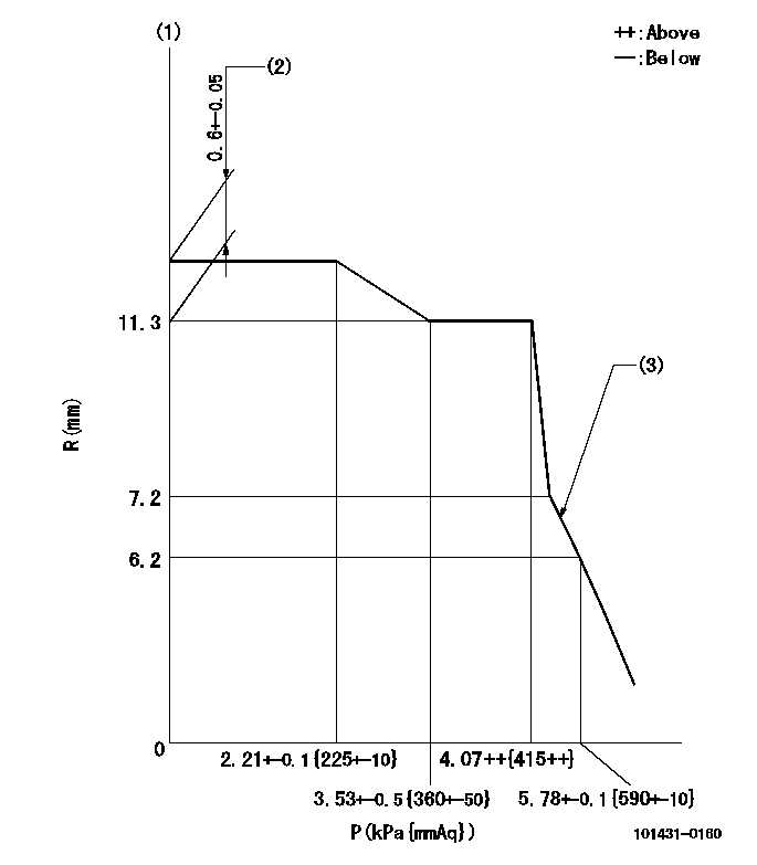
R:Rack position (mm)
P:Negative pressure
(1)Pneumatic governor
(2)Torque control stroke
(3)Beginning of idle sub spring operation: L1
----------
L1=7.2-0.5mm
----------
----------
L1=7.2-0.5mm
----------
Information:
Always determine the cause of the engine shutdown. Make necessary repairs before attempting restarting the engine.
Air Shutoff Solenoid (If Equipped)
This optional solenoid is located on top of the engine in the air inlet system. When the solenoid is activated, the solenoid mechanically shuts off inlet air to the engine. The solenoid can only be activated by the overspeed switch or the emergency stop switch.Fuel Shutoff Solenoid
This solenoid is located on the governor or on the fuel injection pump. When the solenoid is activated, the solenoid moves the fuel rack (either directly or through the governor) to the Fuel Off position.Overspeed Shutoffs
Magnetic pickup (1), mounted in the flywheel housing (2).A magnetic pickup mounted in the flywheel housing senses the passage of the flywheel ring gear teeth. Should the engine speed increase above the overspeed setting of the Electronic Speed Switch (118 percent of rated engine speed), the magnetic pickup will sense the overspeed. The overspeed condition activates both the air (if equipped) and fuel shutoff solenoids.The shutoffs must be reset before the engine will restart. A reset button on the Electronic Speed Switch (in the junction box) must be pushed to open the overspeed switch. The air shutoff lever (at the top of the air inlet housing) must be manually reset.Oil Pressure Switches
Typical example of oil pressure switches, mounted in the rear of the junction box.An oil pressure switch has wires connected to the electrical system for alarm or shutoff functions. The oil pressure switch senses oil pressure at the bearing oil gallery. If sufficient oil pressure is not achieved after engine starting, or if the engine has been running normally and then loses oil pressure, the fuel shutoff solenoid is energized to shut the engine off. No resetting procedure is required.Engine Step Oil Pressure
This is an adjustable engine speed setting that protects the engine from a failure caused by too little oil pressure for a specified speed range. This option requires two different oil pressure switches. One switch has a high pressure rating- when the engine is running above the speed setting, the engine must maintain oil pressure higher than the switch rating. The other switch has a low pressure rating- an engine running below the speed setting must maintain oil pressure above the low switch rating.In an automatic start/stop system, an automatic reset switch is used. Manually operated systems require the switch to be reset before the engine will start.
If the RESET button does not move to the extended position after the engine starts, the engine will NOT be protected by this particular switch.If the RESET button remains in the reset position, the engine oil pump will not develop normal oil pressure. An inspection should be made to correct the problem.
In order to reset the switch, push the RESET button until the button latches. After the engine starts and develops oil pressure, the button will move to the extended (running) position.
The button must be in the RUN position to protect the engine. If the button remains in