Information
ZEXEL
101402-3000
1014023000
KOMATSU
6131711500
6131711500

Rating:
Service parts 101402-3000 INJECTION-PUMP ASSEMBLY:
1.
_
3.
GOVERNOR
5.
AUTOM. ADVANCE MECHANIS
6.
COUPLING PLATE
8.
_
9.
_
11.
Nozzle and Holder
6131-11-3100
12.
Open Pre:MPa(Kqf/cm2)
22.1{225}
15.
NOZZLE SET
Cross reference number
ZEXEL
101402-3000
1014023000
KOMATSU
6131711500
6131711500
Zexel num
Bosch num
Firm num
Name
Calibration Data:
Adjustment conditions
Test oil
1404 Test oil ISO4113 or {SAEJ967d}
1404 Test oil ISO4113 or {SAEJ967d}
Test oil temperature
degC
40
40
45
Nozzle and nozzle holder
105780-8140
Bosch type code
EF8511/9A
Nozzle
105780-0000
Bosch type code
DN12SD12T
Nozzle holder
105780-2080
Bosch type code
EF8511/9
Opening pressure
MPa
17.2
Opening pressure
kgf/cm2
175
Injection pipe
Outer diameter - inner diameter - length (mm) mm 6-2-600
Outer diameter - inner diameter - length (mm) mm 6-2-600
Overflow valve
132424-0620
Overflow valve opening pressure
kPa
157
123
191
Overflow valve opening pressure
kgf/cm2
1.6
1.25
1.95
Tester oil delivery pressure
kPa
157
157
157
Tester oil delivery pressure
kgf/cm2
1.6
1.6
1.6
Direction of rotation (viewed from drive side)
Right R
Right R
Injection timing adjustment
Direction of rotation (viewed from drive side)
Right R
Right R
Injection order
1-2-4-3
Pre-stroke
mm
2.1
2.05
2.15
Beginning of injection position
Governor side NO.1
Governor side NO.1
Difference between angles 1
Cyl.1-2 deg. 90 89.5 90.5
Cyl.1-2 deg. 90 89.5 90.5
Difference between angles 2
Cal 1-4 deg. 180 179.5 180.5
Cal 1-4 deg. 180 179.5 180.5
Difference between angles 3
Cal 1-3 deg. 270 269.5 270.5
Cal 1-3 deg. 270 269.5 270.5
Injection quantity adjustment
Adjusting point
A
Rack position
7.5
Pump speed
r/min
1150
1150
1150
Average injection quantity
mm3/st.
76
75
77
Max. variation between cylinders
%
0
-2
2
Basic
*
Fixing the lever
*
Injection quantity adjustment_02
Adjusting point
B
Rack position
6.4
Pump speed
r/min
350
350
350
Average injection quantity
mm3/st.
14
12.6
15.4
Max. variation between cylinders
%
0
-10
10
Fixing the lever
*
Test data Ex:
Governor adjustment
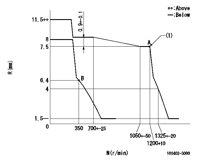
N:Pump speed
R:Rack position (mm)
(1)Supplied with torque spring not set.
----------
----------
----------
----------
Speed control lever angle

F:Full speed
I:Idle
S:Stop
----------
----------
a=11deg+-5deg b=32deg+-3deg c=29deg+-3deg
----------
----------
a=11deg+-5deg b=32deg+-3deg c=29deg+-3deg
Information:
Illustration 1 g06221137
(1) Back flow connector
Illustration 2 g06221138
(2) 423-3253 Connector (Old back flow connector with check valve)
(3) 516-2663 Connector As (PCA connector without check valve)The new and the former connector assembly part numbers are listed in the Table 1.
Table 1
Qty New Part Number Description Former Part Number
1 516-2663 Connector As 423-3253
Illustration 3 g06224488
Bosch Diesel Exhaust Fluid Pump with the part number stamping
The Bosch part number is stamped on the pump, refer to Illustration 3. The Cat® part number equivalent to the Bosch part number for the pump is given in Table 2.
Table 2
Qty Cat® Part Number Description Bosch Part Number
1 485-9753 Diesel Exhaust Fluid Pump Gp (24V) 0 444042168
1 398-4746 Diesel Exhaust Fluid Pump Gp (14 V) 0 444042166 Note: The change is effective on the PETU and DEF pump serial numbers listed in Table 3.
Table 3
PETU Serial No: PET034589M
PUMP Serial No: 0171013500