Information
ZEXEL
101401-9070
1014019070

Rating:
Cross reference number
ZEXEL
101401-9070
1014019070
Zexel num
Bosch num
Firm num
Name
101401-9070
Calibration Data:
Adjustment conditions
Test oil
1404 Test oil ISO4113 or {SAEJ967d}
1404 Test oil ISO4113 or {SAEJ967d}
Test oil temperature
degC
40
40
45
Nozzle and nozzle holder
105780-8140
Bosch type code
EF8511/9A
Nozzle
105780-0000
Bosch type code
DN12SD12T
Nozzle holder
105780-2080
Bosch type code
EF8511/9
Opening pressure
MPa
17.2
Opening pressure
kgf/cm2
175
Injection pipe
Outer diameter - inner diameter - length (mm) mm 6-2-600
Outer diameter - inner diameter - length (mm) mm 6-2-600
Overflow valve
131424-6220
Overflow valve opening pressure
kPa
255
221
289
Overflow valve opening pressure
kgf/cm2
2.6
2.25
2.95
Tester oil delivery pressure
kPa
157
157
157
Tester oil delivery pressure
kgf/cm2
1.6
1.6
1.6
Direction of rotation (viewed from drive side)
Right R
Right R
Injection timing adjustment
Direction of rotation (viewed from drive side)
Right R
Right R
Injection order
1-3-4-2
Pre-stroke
mm
3.6
3.55
3.65
Beginning of injection position
Drive side NO.1
Drive side NO.1
Difference between angles 1
Cal 1-3 deg. 90 89.5 90.5
Cal 1-3 deg. 90 89.5 90.5
Difference between angles 2
Cal 1-4 deg. 180 179.5 180.5
Cal 1-4 deg. 180 179.5 180.5
Difference between angles 3
Cyl.1-2 deg. 270 269.5 270.5
Cyl.1-2 deg. 270 269.5 270.5
Injection quantity adjustment
Adjusting point
-
Rack position
10.2+-0.
5
Pump speed
r/min
1000
1000
1000
Average injection quantity
mm3/st.
46
45
47
Max. variation between cylinders
%
0
-2.5
2.5
Basic
*
Fixing the rack
*
Standard for adjustment of the maximum variation between cylinders
*
Injection quantity adjustment_02
Adjusting point
-
Rack position
9.7+-0.5
Pump speed
r/min
325
325
325
Average injection quantity
mm3/st.
10
8.7
11.3
Max. variation between cylinders
%
0
-10
10
Fixing the rack
*
Standard for adjustment of the maximum variation between cylinders
*
Remarks
Adjust only variation between cylinders; adjust governor according to governor specifications.
Adjust only variation between cylinders; adjust governor according to governor specifications.
Injection quantity adjustment_03
Adjusting point
A
Rack position
R1(10.2)
Pump speed
r/min
1000
1000
1000
Average injection quantity
mm3/st.
46
45
47
Basic
*
Fixing the lever
*
Boost pressure
kPa
36
36
Boost pressure
mmHg
270
270
Injection quantity adjustment_04
Adjusting point
B
Rack position
R1+0.3
Pump speed
r/min
1750
1750
1750
Average injection quantity
mm3/st.
60
56
64
Fixing the lever
*
Boost pressure
kPa
36
36
Boost pressure
mmHg
270
270
Injection quantity adjustment_05
Adjusting point
C
Rack position
R2(R1-0.
3)
Pump speed
r/min
700
700
700
Average injection quantity
mm3/st.
37.7
33.7
41.7
Fixing the lever
*
Boost pressure
kPa
0
0
0
Boost pressure
mmHg
0
0
0
Injection quantity adjustment_06
Adjusting point
D
Rack position
R2+0.4
Pump speed
r/min
500
500
500
Average injection quantity
mm3/st.
30
26
34
Fixing the lever
*
Boost pressure
kPa
0
0
0
Boost pressure
mmHg
0
0
0
Injection quantity adjustment_07
Adjusting point
I
Rack position
-
Pump speed
r/min
100
100
100
Average injection quantity
mm3/st.
67
67
72
Fixing the lever
*
Rack limit
*
Boost compensator adjustment
Pump speed
r/min
700
700
700
Rack position
R1-0.3
Boost pressure
kPa
20
18.7
21.3
Boost pressure
mmHg
150
140
160
Boost compensator adjustment_02
Pump speed
r/min
700
700
700
Rack position
R1(10.2)
Boost pressure
kPa
29.3
22.6
29.3
Boost pressure
mmHg
220
170
220
Timer adjustment
Pump speed
r/min
-
Advance angle
deg.
0
0
0
Remarks
Measure speed (beginning of operation).
Measure speed (beginning of operation).
Timer adjustment_02
Pump speed
r/min
1750
Advance angle
deg.
4
3.5
4.5
Remarks
Finish
Finish
Test data Ex:
Governor adjustment
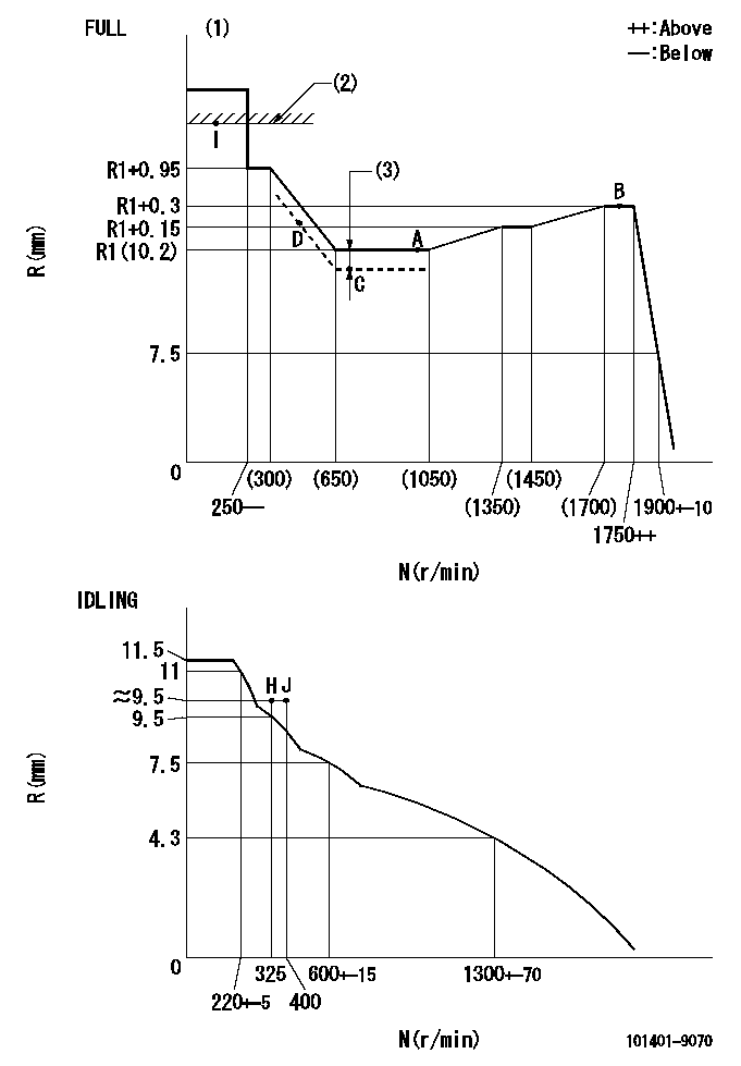
N:Pump speed
R:Rack position (mm)
(1)Torque cam stamping: T1
(2)RACK LIMIT
(3)Boost compensator stroke: BCL
----------
T1=B88 BCL=0.3+-0.1mm
----------
----------
T1=B88 BCL=0.3+-0.1mm
----------
Speed control lever angle

F:Full speed
I:Idle
(1)Use the hole at R = aa
(2)Stopper bolt set position 'H'
----------
aa=40mm
----------
a=26deg+-5deg b=42deg+-3deg
----------
aa=40mm
----------
a=26deg+-5deg b=42deg+-3deg
Stop lever angle

N:Engine manufacturer's normal use
S:Stop the pump.
(1)Free (at shipping)
(2)Use the hole at R = aa
(3)Rack position corresponding to bb
(4)Set the stopper bolt at speed = cc and rack position = dd.
(5)After setting the stopper bolt, confirm non-injection at speed ee. (Rack position = ff or less)
----------
aa=54mm bb=16mm cc=1700r/min dd=6.5-0.5mm ee=325r/min ff=8mm
----------
a=2deg+-5deg b=15deg+-5deg c=25deg+-5deg
----------
aa=54mm bb=16mm cc=1700r/min dd=6.5-0.5mm ee=325r/min ff=8mm
----------
a=2deg+-5deg b=15deg+-5deg c=25deg+-5deg
0000001501 MICRO SWITCH
Adjustment of the micro-switch
Adjust the bolt to obtain the following lever position when the micro-switch is ON.
(1)Speed N1
(2)Rack position Ra
----------
N1=950+-5r/min Ra=8mm
----------
----------
N1=950+-5r/min Ra=8mm
----------
Timing setting

(1)Pump vertical direction
(2)Position of gear mark '3' at No 1 cylinder's beginning of injection
(3)B.T.D.C.: aa
(4)-
----------
aa=11deg
----------
a=(130deg)
----------
aa=11deg
----------
a=(130deg)
Information:
Transmission Oil Cooler
The machine is equipped with a power shift transmission. A transmission oil cooler is installed in the outlet section of the radiator. The radiator coolant flows around the tubes of the cooler and cools the transmission oil as it flows through the cooler. The transmission oil then returns to the transmission inlet.Lubrication System
Oil Pump
(1) Strainer. (2) Oil pump relief valve. (3) Oil pump. (4) Idler gear. (5) Crankshaft gear.The lubrication system is the pressure type and the flow of oil goes from the oil pan through strainer (1) into oil pump (3). Oil pump (3) is driven by crankshaft gear (5) through the idler gear (4). The oil pump is connected to the front main bearing cap. Relief valve (2) which is spring loaded controls the maximum oil pressure. An oil pressure sending unit is connected to the main oil gallery.Oil under pressure goes from the oil pump through the relief valve, oil filter and into the main oil gallery that is a drilled passage the length of the crankcase. From the gallery the oil flows through drilled passages to the main bearing bores and then through the crankshaft passages to the big end (rod) bearings. The small end (rod) bearings, cylinder liners and pistons get splash lubrication from the big end (rod) bearings.The camshaft front bearing and journals are lubricated from numbers 1, 3 and 5 main bearings. The camshaft center journal supplies a controlled amount of oil to the rocker shaft assembly. Oil from the rocker shaft drains through a bleed hole in each rocker lever to lubricate the valves, guides, tappets (valve lifters) and cam lobes.
Timing Gears
(6) Idler gear. (7) Idler gear retainer plate.Oil also goes from the gallery through the rear of idler gear (6) hub, then through passages to lubricate the idler gear bearing and gear retainer plate (7). On engines equipped with hydraulic governed fuel injection pumps, the fuel pump adapter plate is also lubricated from the main oil gallery. The timing gears are splash lubricated from the idler gear hub.
Oil Lubrication SchematicAir Inlet And Exhaust System
Air Inlet Components
(1) Intake manifold. (2) Exhaust manifold.
Air Inlet Components
(3) Air cleaner.The air inlet and exhaust system components are: air cleaner (3), intake manifold (1), an air inlet hose, an air indicator, the cylinder head valves and valve mechanism components, exhaust manifold (2), pipe and muffler.Air is pulled in the air inlet system by the intake stroke of the piston. The air flows in air cleaner (3), through air inlet hose that directs the volume of air to intake manifold (1). The air flows through intake manifold (1) which directs even distribution of the air to each cylinder where the air is mixed with fuel from the injectors. The sequence and action of the engines' four cylinders and four strokes, (compression, power, exhaust and intake) give constant air flow to the intake system for engine operation.An air indicator located on the air inlet hose shows a red indication when too much air restriction (dirt)
Have questions with 101401-9070?
Group cross 101401-9070 ZEXEL
Mazda
Mazda
Mazda
Mazda
Mazda
Mitsubishi-Heav
Dpico
101401-9070