Information
BOSCH
F 01G 29M 01W
f01g29m01w
ZEXEL
101044-8360
1010448360

Rating:
Scheme ###:
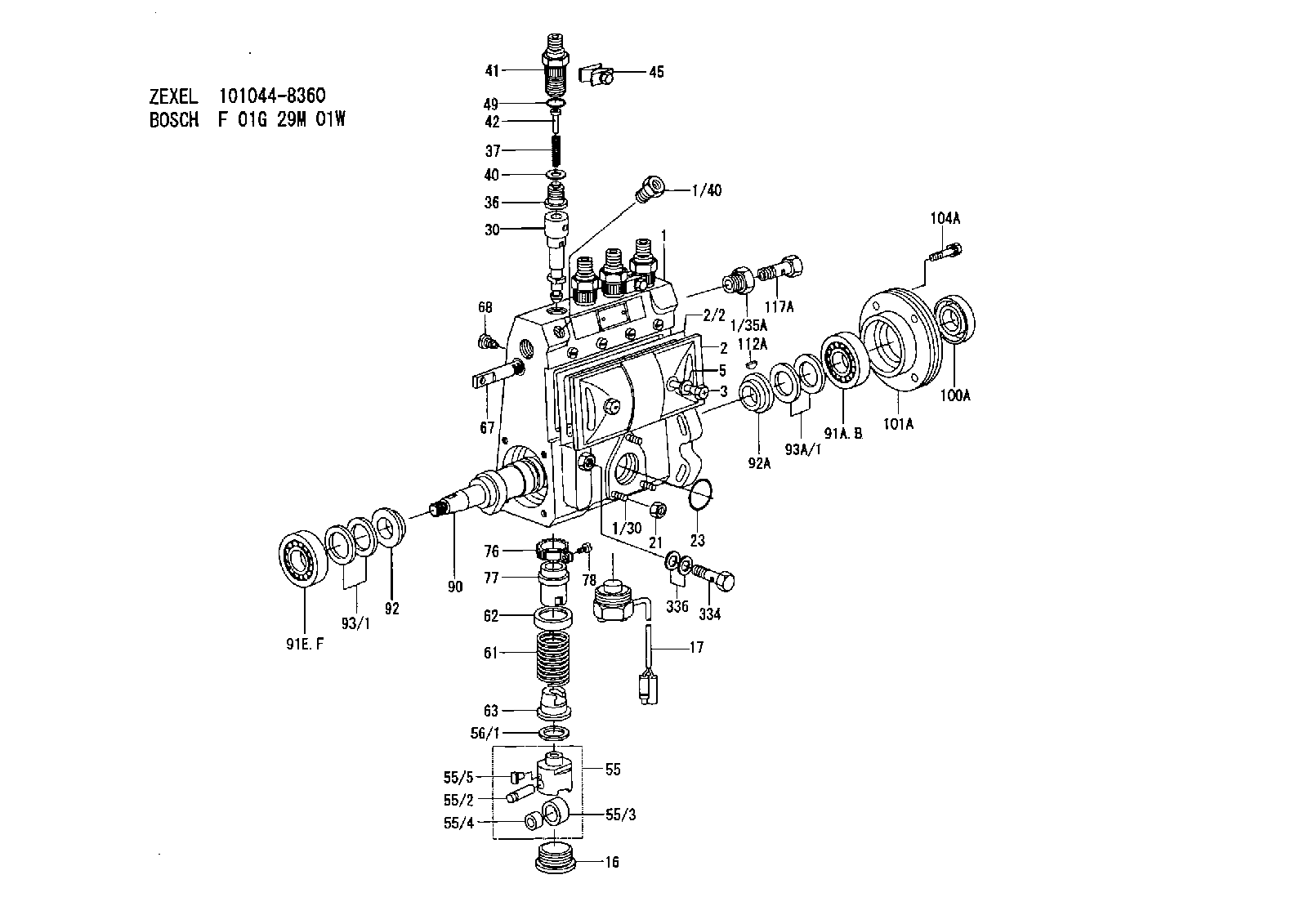
| 1. | [1] | 131062-7820 | PUMP HOUSING |
| 1/30. | [3] | 029040-6020 | STUD |
| 1/35A. | [1] | 131400-0100 | ADAPTOR |
| 1/40. | [1] | 131002-2000 | ADAPTOR |
| 2. | [1] | 131028-6220 | COVER |
| 2/2. | [1] | 131011-1900 | GASKET |
| 3. | [2] | 131017-1000 | FLAT-HEAD SCREW |
| 5. | [2] | 029340-6020 | GASKET |
| 16. | [3] | 131034-1401 | CAPSULE |
| 17. | [1] | 131034-3100 | PULSE GENERATOR |
| 21. | [3] | 139206-0400 | UNION NUT |
| 23. | [1] | 029633-1010 | O-RING |
| 30. | [4] | 131152-7420 | PLUNGER-AND-BARREL ASSY A211 |
| 36. | [4] | 131110-4720 | DELIVERY-VALVE ASSEMBLY A28 |
| 37. | [4] | 131112-2300 | COILED SPRING |
| 40. | [4] | 131115-1600 | GASKET |
| 41. | [4] | 131116-7600 | FITTING |
| 42. | [4] | 131117-2300 | FILLER PIECE |
| 45. | [2] | 131122-0520 | PLATE |
| 49. | [4] | 029632-0030 | O-RING |
| 55. | [4] | 131200-0220 | TAPPET |
| 55/2. | [4] | 131203-0200 | BEARING PIN |
| 55/3. | [4] | 131204-1000 | ROLLER |
| 55/4. | [4] | 131205-0500 | BUSHING |
| 55/5. | [4] | 131206-0200 | SLIDER |
| 56/1. | [0] | 029311-0020 | SHIM D19&10T0.30 |
| 56/1. | [0] | 029311-0030 | SHIM D19&10T0.40 |
| 56/1. | [0] | 029311-0040 | SHIM D19&10T0.50 |
| 56/1. | [0] | 029311-0050 | SHIM D19&10T0.6 |
| 56/1. | [0] | 029311-0060 | SHIM D19&10T0.7 |
| 56/1. | [0] | 029311-0070 | SHIM D19&10T0.8 |
| 56/1. | [0] | 029311-0080 | SHIM D19&10T0.9 |
| 56/1. | [0] | 029311-0090 | SHIM D19&10T1 |
| 56/1. | [0] | 029311-0110 | SHIM D19&10T1.1 |
| 56/1. | [0] | 029311-0120 | SHIM D19&10T1.2 |
| 56/1. | [0] | 029311-0130 | SHIM D19&10T1.3 |
| 56/1. | [0] | 029311-0140 | SHIM D19&10T1.4 |
| 56/1. | [0] | 029311-0270 | SHIM D19&10T0.55 |
| 56/1. | [0] | 029311-0280 | SHIM D19&10T0.65 |
| 56/1. | [0] | 029311-0290 | SHIM D19&10T0.75 |
| 56/1. | [0] | 029311-0310 | SHIM D19&10T0.85 |
| 56/1. | [0] | 029311-0320 | SHIM D19&10T0.95 |
| 56/1. | [0] | 029311-0330 | SHIM D19&10T1.05 |
| 56/1. | [0] | 029311-0340 | SHIM D19&10T1.15 |
| 56/1. | [0] | 029311-0350 | SHIM D19&10T1.25 |
| 56/1. | [0] | 029311-0490 | SHIM D19&10T1.5 |
| 56/1. | [0] | 029311-0500 | SHIM D19&10T1.6 |
| 56/1. | [0] | 029311-0580 | SHIM D19&10T0.2 |
| 56/1. | [0] | 029311-0590 | SHIM D19&10T0.25 |
| 56/1. | [0] | 029311-0600 | SHIM D19&10T0.35 |
| 56/1. | [0] | 029311-0610 | SHIM D19&10T0.45 |
| 56/1. | [0] | 029311-0620 | SHIM D19&10T1.35 |
| 56/1. | [0] | 029311-0630 | SHIM D19&10T1.45 |
| 56/1. | [0] | 029311-0710 | SHIM D19&10T1.55 |
| 61. | [4] | 131215-2500 | COMPRESSION SPRING |
| 62. | [4] | 131216-0100 | SLOTTED WASHER |
| 63. | [4] | 131217-0200 | SLOTTED WASHER |
| 67. | [1] | 131254-0000 | CONTROL RACK |
| 68. | [1] | 131226-0300 | FLAT-HEAD SCREW |
| 76. | [4] | 131240-0100 | PINION |
| 77. | [4] | 131241-0100 | CONTROL SLEEVE |
| 78. | [4] | 131242-0100 | FLAT-HEAD SCREW |
| 90. | [1] | 131360-2500 | CAMSHAFT |
| 91A. | [1] | 016630-2030 | BEARING PLATE HR30203J(NSK) |
| 91B. | [1] | 028201-7020 | BEARING PLATE 4T-30203E1(TOYO) |
| 91E. | [1] | 016630-2030 | BEARING PLATE HR30203J(NSK) |
| 91F. | [1] | 028201-7020 | BEARING PLATE 4T-30203E1(TOYO) |
| 92. | [1] | 131302-0300 | SPACER RING |
| 92A. | [1] | 131302-0300 | SPACER RING |
| 93/1. | [0] | 029311-7010 | SHIM D22&17T0.1 |
| 93/1. | [0] | 029311-7020 | SHIM D22&17T0.12 |
| 93/1. | [0] | 029311-7030 | SHIM D22&17T0.14 |
| 93/1. | [0] | 029311-7040 | SHIM D22&17T0.16 |
| 93/1. | [0] | 029311-7050 | SHIM D22&17T0.18 |
| 93/1. | [0] | 029311-7060 | SHIM D22&17T0.5 |
| 93/1. | [0] | 029311-7070 | SHIM D22&17T1.0 |
| 93/1. | [0] | 029311-7090 | SHIM D22&17T0.3 |
| 93/1. | [0] | 029311-7210 | SHIM D22&17T0.7 |
| 93/1. | [0] | 029311-7220 | SHIM D22&17T1.4 |
| 93/1. | [0] | 139417-0000 | SHIM D22&17T2.4 |
| 93A/1. | [0] | 029311-7010 | SHIM D22&17T0.1 |
| 93A/1. | [0] | 029311-7020 | SHIM D22&17T0.12 |
| 93A/1. | [0] | 029311-7030 | SHIM D22&17T0.14 |
| 93A/1. | [0] | 029311-7040 | SHIM D22&17T0.16 |
| 93A/1. | [0] | 029311-7050 | SHIM D22&17T0.18 |
| 93A/1. | [0] | 029311-7060 | SHIM D22&17T0.5 |
| 93A/1. | [0] | 029311-7070 | SHIM D22&17T1.0 |
| 93A/1. | [0] | 029311-7090 | SHIM D22&17T0.3 |
| 93A/1. | [0] | 029311-7210 | SHIM D22&17T0.7 |
| 93A/1. | [0] | 029311-7220 | SHIM D22&17T1.4 |
| 93A/1. | [0] | 139417-0000 | SHIM D22&17T2.4 |
| 100A. | [1] | 029621-7050 | PACKING RING |
| 101A. | [1] | 131330-6200 | COVER |
| 104A. | [4] | 020006-1440 | BLEEDER SCREW |
| 112A. | [1] | 025803-1640 | WOODRUFF KEY |
| 117A. | [1] | 029731-4080 | EYE BOLT |
| 334. | [1] | 029731-0120 | EYE BOLT |
| 336. | [2] | 026510-1340 | GASKET |
Cross reference number
Zexel num
Bosch num
Firm num
Name
Information:
start by: a) remove fuel injection lines 1. Remove cover (1) from the front of the timing gear cover. Remove bolt (2) and washer (3). Install bolt (2) again to the position shown. Use tool (A) to loosen the pump drive gear from the camshaft. Remove tool (A) and bolt (2).2. Remove the governor linkage. Disconnect the fuel supply line. 3. Remove inlet oil tube (4) for the turbocharger.4. Disconnect the air tube from the fuel ratio control.5. Disconnect hose (5).6. Disconnect the three drain tubes from the fuel injection pump housing.7. Remove bracket (6).8. Remove the three nuts that hold the fuel injection pump housing and governor to the timing plate.9. Remove the fuel injection pump housing and governor.Install Fuel Injection Pump Housing And Governor
1. Use the following procedures to put the No. 1 piston at top center on the compression stroke. No. 1 piston at top center (TC) on the compression stroke is the starting point for all timing procedures. The engine is seen from the flywheel end when direction of flywheel rotation is given.a) Turn the flywheel approximately 30 degrees clockwise. The reason for making this step is to be sure the play is removed from the timing gears when the engine is put on top center. b) For engines with a timing pointer, remove the cover on the flywheel housing. Turn the flywheel counterclockwise until the "TC 1" mark on the flywheel is in alignment with the pointer.c) For engines with a timing bolt, turn the flywheel counterclockwise until a 3/8-16 NC bolt can be installed in the flywheel through the hole in the flywheel housing. Do not turn the flywheel backwards.d) Remove the breather from the valve cover. The rocker arms for No. 1 piston can be seen through the breather hole in the valve cover.e) Check to see if both rocker arms for the No. 1 piston can be moved backward and forward by hand. The No. 1 piston is at top center on the compression stroke when the "TC 1" mark on the flywheel is in alignment with the pointer, or the bolt can be put in the flywheel through the hole in the flywheel housing, and both rocker arms for the No. 1 piston can be moved backward and forward by hand. f) If both rocker arms can not be moved by hand, the No. 1 piston is not at top center on the compression stroke. Turn the flywheel counterclockwise one full turn (360°). For engines with a timing pointer, the "TC 1" mark on the flywheel must then be in alignment with the pointer. For engines with a timing bolt, the bolt must be installed in the flywheel through the hole in the flywheel housing.2. For engines with a timing pointer, turn the flywheel counterclockwise until the pointer is between the 1° and 2° mark on the flywheel as shown. 3. For engines with a timing bolt, do not turn the flywheel past this position. 4. Remove the
1. Use the following procedures to put the No. 1 piston at top center on the compression stroke. No. 1 piston at top center (TC) on the compression stroke is the starting point for all timing procedures. The engine is seen from the flywheel end when direction of flywheel rotation is given.a) Turn the flywheel approximately 30 degrees clockwise. The reason for making this step is to be sure the play is removed from the timing gears when the engine is put on top center. b) For engines with a timing pointer, remove the cover on the flywheel housing. Turn the flywheel counterclockwise until the "TC 1" mark on the flywheel is in alignment with the pointer.c) For engines with a timing bolt, turn the flywheel counterclockwise until a 3/8-16 NC bolt can be installed in the flywheel through the hole in the flywheel housing. Do not turn the flywheel backwards.d) Remove the breather from the valve cover. The rocker arms for No. 1 piston can be seen through the breather hole in the valve cover.e) Check to see if both rocker arms for the No. 1 piston can be moved backward and forward by hand. The No. 1 piston is at top center on the compression stroke when the "TC 1" mark on the flywheel is in alignment with the pointer, or the bolt can be put in the flywheel through the hole in the flywheel housing, and both rocker arms for the No. 1 piston can be moved backward and forward by hand. f) If both rocker arms can not be moved by hand, the No. 1 piston is not at top center on the compression stroke. Turn the flywheel counterclockwise one full turn (360°). For engines with a timing pointer, the "TC 1" mark on the flywheel must then be in alignment with the pointer. For engines with a timing bolt, the bolt must be installed in the flywheel through the hole in the flywheel housing.2. For engines with a timing pointer, turn the flywheel counterclockwise until the pointer is between the 1° and 2° mark on the flywheel as shown. 3. For engines with a timing bolt, do not turn the flywheel past this position. 4. Remove the