Information eye bolt
BOSCH
9 442 610 613
9442610613
ZEXEL
029731-0140
0297310140
ISUZU
9812151460
9812151460
Rating:
Include in #1:
106661-0754
as _
Include in ###:
Cross reference number
Zexel num
Bosch num
Firm num
Name
029731-0140
9 442 610 613
9812151460 ISUZU
EYE BOLT
D 90HY EYE BOLT Standard parts Others
D 90HY EYE BOLT Standard parts Others
029731-0140
9 442 610 613
6073120030 HINO
EYE BOLT
D 90HY EYE BOLT Standard parts Others
D 90HY EYE BOLT Standard parts Others
029731-0140
9 442 610 613
6073122830 HINO
EYE BOLT
A D 90HY EYE BOLT Standard parts Others
A D 90HY EYE BOLT Standard parts Others
029731-0140
9 442 610 613
1675737501 NISSAN
EYE BOLT
D 90HY EYE BOLT Standard parts Others
D 90HY EYE BOLT Standard parts Others
029731-0140
9 442 610 613
1675737501 NISSAN-DIESEL
EYE BOLT
D 90HY EYE BOLT Standard parts Others
D 90HY EYE BOLT Standard parts Others
029731-0140
9 442 610 613
1312360800 ISHIKAWAJIMA-S
EYE BOLT
D 90HY EYE BOLT Standard parts Others
D 90HY EYE BOLT Standard parts Others
Information:
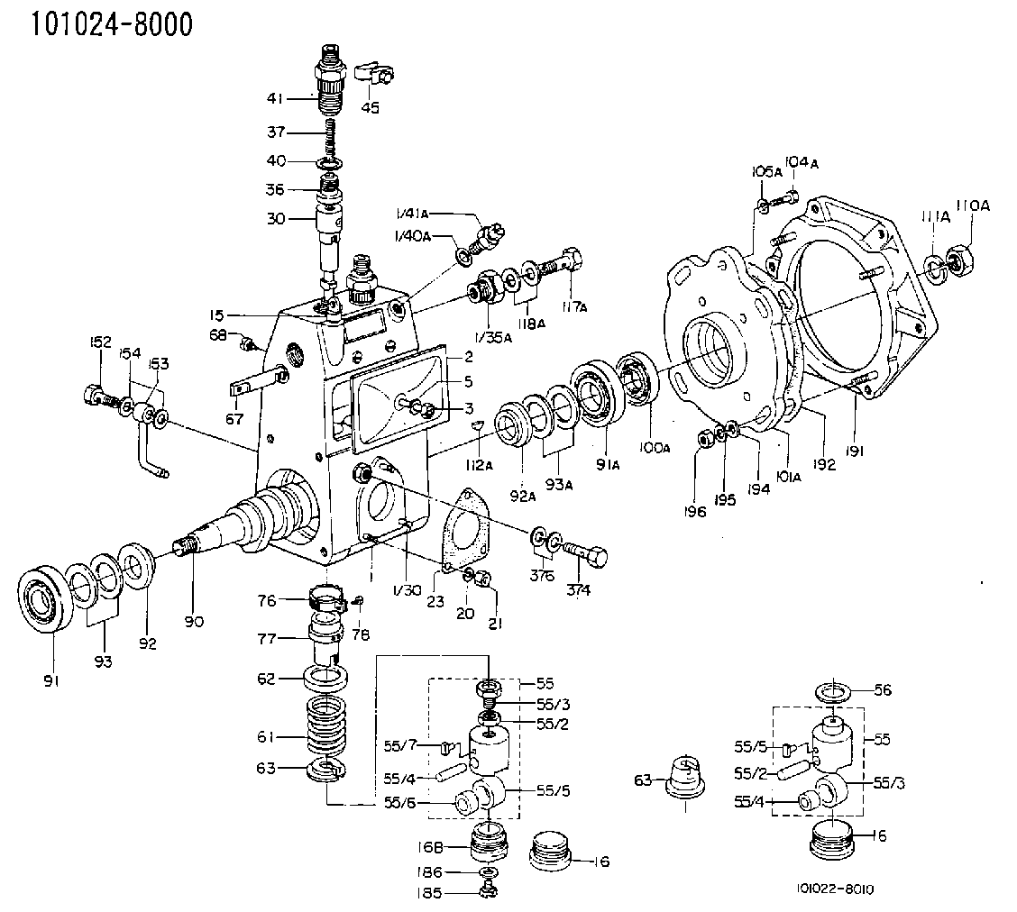
start by:a) remove fuel injection pump housing and governor 1. Install the fuel injection pump housing on tool (A).2. Remove the bolts (1) that hold the governor housing (2) to the fuel injection pump housing.3. Remove the governor housing (2). 4. Remove two springs (4) and the seat (5) from the governor housing.5. Remove the seat (7) from the shaft.6. Remove the spring (6) from the shaft.7. Remove the cover (3) from the pump housing. 8. Remove the shaft (8) and the lever (9) from the pump housing. 9. Remove the thrust collar (11) from the shaft.10. Remove the cover (10) from the pump housing. 11. Loosen the two bolts (13) that hold the torque spring assembly (12) and remove it from the pump housing. 12. Remove the pin (15) from the pump housing.13. Remove the screw (14) and the nut (16) from the pump housing.14. Remove the ring that holds the lever and remove the lever (18) from the dowel (17).15. Remove the dowel (17) from the pump housing. Dowel does not need to be removed unless camshaft is to be removed.
Pull on the shield only a small amount in each location so it will not have distortion or damage. A damaged shield must be replaced.
16. Remove the shield (19) from the camshaft with tool (B). 17. Install the timing pin (C) to hold the camshaft.18. Remove the bolts (20) that hold the flyweight assembly to the camshaft. 19. Remove the flyweight assembly (21) from the camshaft.20. Remove the timing pin (C) from the pump housing.Connection Of Governor To Fuel Injection Pump Housing
1. Put the fuel injection pump housing on the bracket assembly (A).2. Install the timing pin (B) to hold the camshaft.3. Put the flyweight assembly (1) in position on the camshaft. Be sure the pin that holds the shaft (2) is in position on the back of the flyweight assembly.4. Install the bolts that hold the flyweight assembly to the camshaft and tighten to a torque of 10 2 lb. ft. (1.38 0.28 mkg).5. Remove the timing pin (B). 6. Put the shield (3) in position over the flyweights. 7. Use the driver (C) to install the shield the remainder of the way on to the camshaft. 8. Put a new O-ring seal on the dowel (4) and install the dowel in the pump housing. Make the dowel even with the machined surface of the counterbore on the outside of the housing. 9. Put the lever (8) on the dowel (4) and install the ring that holds it on the dowel.10. Install the screw (6) and the nut (7) in the pump housing.11. Install the pin (5) in the pump housing. 12. Put the torque spring assembly (10) in position on the housing and tighten the two bolts (11) that hold it to the housing.13. Install the cover (9) on the pump housing. 14. Put the thrust collar (13) in position between the flyweights. Lift the flyweights up with a piece of wire
Have questions with 029731-0140?
Group cross 029731-0140 ZEXEL
Isuzu
029731-0140
9 442 610 613
9812151460
EYE BOLT
Hino
029731-0140
9 442 610 613
6073120030
EYE BOLT
029731-0140
9 442 610 613
6073122830
EYE BOLT
Nissan
029731-0140
9 442 610 613
1675737501
EYE BOLT
Nissan-Diesel
029731-0140
9 442 610 613
1675737501
EYE BOLT
Ishikawajima-S
029731-0140
9 442 610 613
1312360800
EYE BOLT