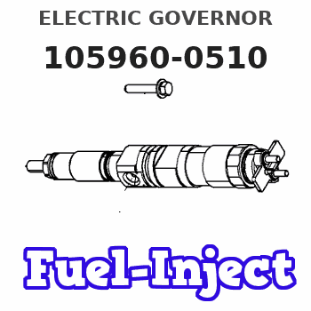
Information electric governor
BOSCH
F 019 Z3E 753
f019z3e753
ZEXEL
105960-0510
1059600510
ISUZU
1157901860
1157901860
Rating:
Scheme ###:
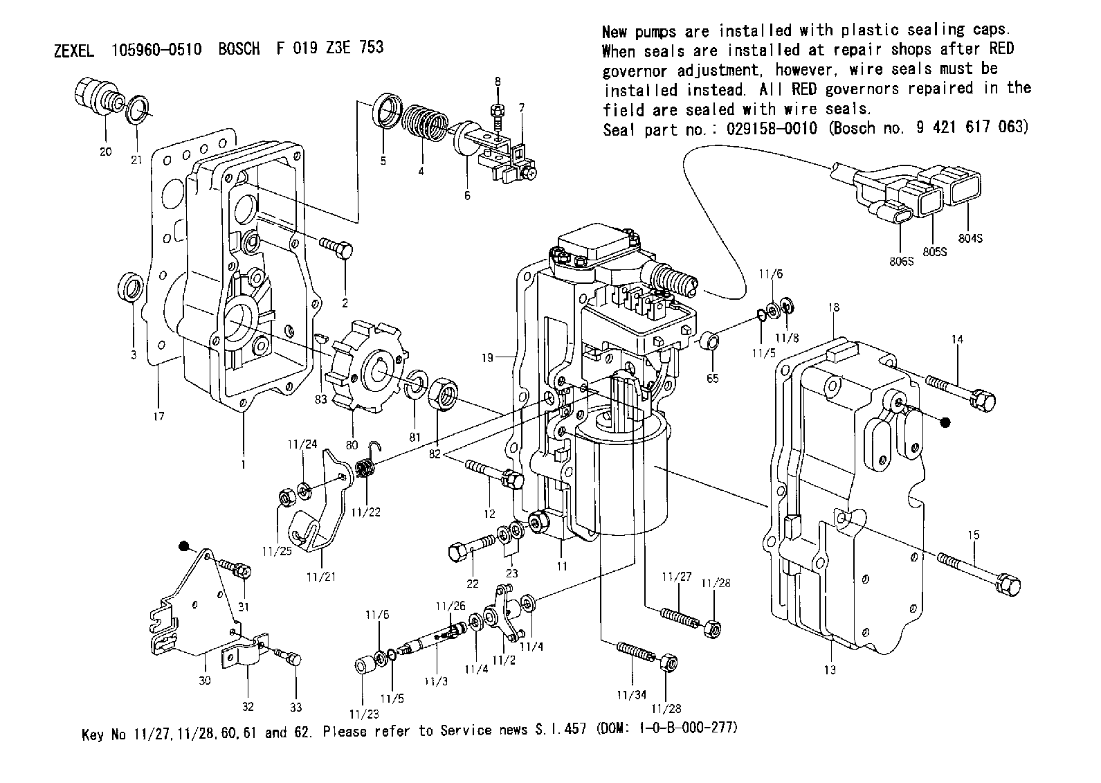
| 1. | [1] | 159560-0100 | GOVERNOR HOUSING |
| 2. | [8] | 139006-4100 | BLEEDER SCREW |
| 3. | [1] | 029621-7050 | PACKING RING |
| 4. | [1] | 159635-8500 | COILED SPRING |
| 5. | [1] | 159564-4000 | SLOTTED WASHER |
| 6. | [1] | 159564-4100 | SLOTTED WASHER |
| 7. | [1] | 159636-3121 | CONNECTOR |
| 7B. | [1] | 159636-3321 | CONNECTOR |
| 7C. | [1] | 159636-3521 | CONNECTOR |
| 8. | [1] | 020105-1240 | BLEEDER SCREW |
| 11. | [1] | 159620-8220 | ACTUATOR |
| 11/2. | [1] | 159583-1020 | STRAP |
| 11/3. | [1] | 159563-1700 | LEVER SHAFT |
| 11/4. | [2] | 029311-0170 | SHIM |
| 11/4. | [2] | 029311-0170 | SHIM |
| 11/5. | [2] | 159635-0200 | O-RING |
| 11/5. | [2] | 159635-0200 | O-RING |
| 11/6. | [2] | 014011-0140 | PLAIN WASHER |
| 11/6. | [2] | 014011-0140 | PLAIN WASHER |
| 11/8. | [1] | 016010-0940 | LOCKING WASHER |
| 11/21. | [1] | 159583-5500 | CONTROL LEVER |
| 11/22. | [1] | 159563-4800 | COILED SPRING |
| 11/23. | [1] | 159563-1800 | BUSHING |
| 11/24. | [1] | 014110-8440 | LOCKING WASHER D15.4&8.2T2 |
| 11/25. | [1] | 013030-8140 | UNION NUT |
| 11/26. | [1] | 159563-1000 | FLAT-HEAD SCREW |
| 11/27. | [1] | 139006-9800 | FLAT-HEAD SCREW |
| 11/27. | [1] | 155615-1700 | FLAT-HEAD SCREW |
| 11/28. | [2] | 013020-6040 | UNION NUT |
| 11/28. | [2] | 013020-6040 | UNION NUT |
| 11/32. | [2] | 020106-1440 | BLEEDER SCREW |
| 11/34. | [1] | 139006-9900 | FLAT-HEAD SCREW |
| 11/34. | [1] | 159563-8400 | FLAT-HEAD SCREW |
| 12. | [2] | 020106-4040 | BLEEDER SCREW |
| 13. | [1] | 159561-1300 | GOVERNOR COVER |
| 14. | [6] | 139006-9400 | BLEEDER SCREW |
| 15. | [2] | 139006-9200 | BLEEDER SCREW |
| 17. | [1] | 154371-5600 | GASKET |
| 18. | [1] | 159635-0100 | GASKET |
| 19. | [1] | 154390-0500 | GASKET |
| 20. | [1] | 153021-5000 | CAP |
| 21. | [1] | 026524-3040 | GASKET |
| 22. | [1] | 159564-0800 | EYE BOLT |
| 23. | [2] | 139514-0000 | GASKET |
| 30. | [1] | 159586-7820 | BRACKET |
| 31. | [3] | 020106-1240 | BLEEDER SCREW |
| 32. | [1] | 159586-2600 | CLAMPING BAND |
| 33. | [2] | 020106-1240 | BLEEDER SCREW |
| 65. | [2] | 159635-0400 | BUSHING |
| 80. | [1] | 159564-8600 | TOOTHED GEAR |
| 81. | [1] | 014111-2420 | LOCKING WASHER |
| 82. | [1] | 013031-2120 | UNION NUT |
| 83. | [1] | 025803-1310 | WOODRUFF KEY 13 MM |
| 804S. | [1] | 159911-2300 | PLUG HOUSING |
| 805S. | [1] | 159911-2400 | PLUG HOUSING |
| 806S. | [1] | 159911-2500 | PLUG HOUSING |
Cross reference number
Zexel num
Bosch num
Firm num
Name
105960-0510
F 019 Z3E 753
1157901860 ISUZU
ELECTRIC GOVERNOR
K 14JE ELECTRIC GOVERNOR GOV
K 14JE ELECTRIC GOVERNOR GOV
Information:
Install the pump cover onto the pump housing. Tighten the four middle bolts. Then, tighten the end bolts in a crisscross pattern. Tighten the bolts to a torque of 10.2 N m (90 lb in).Note: Make sure that the gasket is in place between the housing and the cover.
Repeat Step 1 and Step 2 in order to confirm the electrical connection for the pump coil was not damaged during the removal of the pump cover.
Install the oil inlet line adapter, inlet line, and harness connector to the pump.Note: After the HEUI pump is replaced or reassembled, the engine must be cranked for an extended length of time to fill the pump with oil.Note: Clear any diagnostic or event codes that activated during the initial start-up.
If the engine would not start before inspecting for debris and no debris was found in the HEUI pump, return to Step D in the diagnostic flow chart.If the engine would start before inspecting for debris and no debris was found in the HEUI pump, return to Step L in the diagnostic flow chart.If the pump is to be replaced, complete the checklist form in Special Instruction, REHS5031 that is provided with the service replacement part and insert the completed form back into the box containing the part that is being returned. Proceed to the section of this instruction titled "Oil Rail Cleaning Procedure" for the correct engine size that is being serviced.Oil Rail Cleaning Procedure For the C7 Engine
Illustration 12 g02702636
C7 Cylinder Head
Illustration 13 g02708256
The oil and fuel passages are the same for both the C7 and C9.
(6) Oil Rail for a HEUI fuel system
(7) Oil passage to injector bore
(8) Fuel passage
(9) Injector bore Note: Contain any oil and cleaner that will flow from the cylinder and the lines during the following process. Properly dispose of the oil and contaminated cleaner when work is complete.
Remove fuel injectors. Refer to Disassembly and Assembly for specific machine.
Install six plugs 9U-7080 Tapered Cap/Plug into the lower injector bores. The plugs will prevent oil, cleaners, and debris from entering the cylinders.
Remove the plugs from the front and rear of the cylinder head main oil gallery
Remove the pressure sensor from the cylinder head. Protect the sensor.
Clean out the two rail drain holes by removing their plugs and using the brake cleaner and long squirting straw to flush these passages to the oil rail.
Using the solvent gun with and without the
Have questions with 105960-0510?
Group cross 105960-0510 ZEXEL
Isuzu
105960-0510
F 019 Z3E 753
1157901860
ELECTRIC GOVERNOR