Information electric governor
BOSCH
F 019 Z6E 021
f019z6e021
ZEXEL
105960-0431
1059600431
ISUZU
1157901280
1157901280
Rating:
Scheme ###:
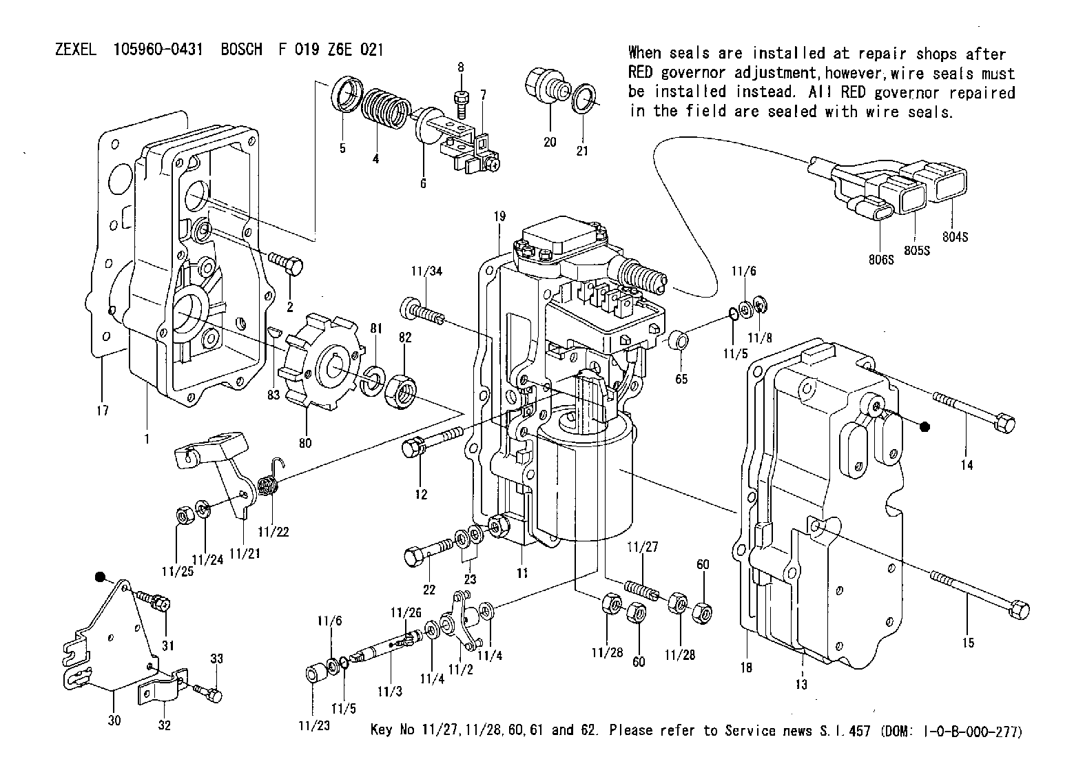
| 1. | [1] | 159560-0100 | GOVERNOR HOUSING |
| 2. | [8] | 139006-4100 | BLEEDER SCREW |
| 4. | [1] | 159635-8500 | COILED SPRING |
| 5. | [1] | 159564-4000 | SLOTTED WASHER |
| 6. | [1] | 159635-8800 | SLOTTED WASHER |
| 7. | [1] | 159636-3121 | CONNECTOR |
| 7B. | [1] | 159636-3321 | CONNECTOR |
| 7C. | [1] | 159636-3521 | CONNECTOR |
| 8. | [1] | 020105-1240 | BLEEDER SCREW M5P0.8L12 |
| 11. | [1] | 159620-6222 | ACTUATOR |
| 11/2. | [1] | 159583-1020 | STRAP |
| 11/3. | [1] | 159563-1700 | LEVER SHAFT |
| 11/4. | [2] | 029311-0170 | SHIM |
| 11/4. | [2] | 029311-0170 | SHIM |
| 11/5. | [2] | 159635-0200 | O-RING |
| 11/5. | [2] | 159635-0200 | O-RING |
| 11/6. | [2] | 014011-0140 | PLAIN WASHER D22&10.5T1.6 |
| 11/6. | [2] | 014011-0140 | PLAIN WASHER D22&10.5T1.6 |
| 11/8. | [1] | 016010-0940 | LOCKING WASHER |
| 11/10. | [4] | 139006-9100 | BLEEDER SCREW |
| 11/11. | [1] | 407914-2000 | CONTROL UNIT |
| 11/12. | [4] | 010235-1640 | HEX-SOCKET-HEAD CAP SCREW |
| 11/14. | [4] | 029300-5020 | PLAIN WASHER D10&5.1T1.5 |
| 11/15. | [1] | 159636-0500 | LIP |
| 11/18. | [2] | 020105-1640 | BLEEDER SCREW M5P0.8L16 |
| 11/19. | [1] | 134002-0200 | ADAPTOR |
| 11/21. | [1] | 159583-5600 | CONTROL LEVER |
| 11/22. | [1] | 159563-4800 | COILED SPRING |
| 11/23. | [1] | 159563-1800 | BUSHING |
| 11/24. | [1] | 014110-8440 | LOCKING WASHER |
| 11/25. | [1] | 013030-8140 | UNION NUT M8P1.25H5 |
| 11/26. | [1] | 159563-1000 | FLAT-HEAD SCREW |
| 11/27. | [1] | 139006-9800 | FLAT-HEAD SCREW |
| 11/28. | [2] | 013020-6040 | UNION NUT M6P1H5 |
| 11/28. | [2] | 013020-6040 | UNION NUT M6P1H5 |
| 11/32. | [2] | 020106-1440 | BLEEDER SCREW M6P1.0L14 |
| 11/34. | [1] | 139006-9900 | FLAT-HEAD SCREW |
| 11/39. | [2] | 159635-5200 | SEAL RING |
| 11/40. | [4] | 020106-2840 | BLEEDER SCREW |
| 12. | [2] | 020106-4040 | BLEEDER SCREW |
| 13. | [1] | 159561-1400 | GOVERNOR COVER |
| 14. | [6] | 139006-9400 | BLEEDER SCREW |
| 15. | [2] | 139006-9200 | BLEEDER SCREW |
| 17. | [1] | 154371-5600 | GASKET |
| 18. | [1] | 159635-0100 | GASKET |
| 19. | [1] | 154390-0500 | GASKET |
| 20. | [1] | 153021-5000 | CAP |
| 21. | [1] | 026524-3040 | GASKET |
| 22. | [1] | 159564-0800 | EYE BOLT |
| 23. | [2] | 139514-0000 | GASKET D19.2&14.2T1.0 |
| 30. | [1] | 159586-7820 | BRACKET |
| 31. | [3] | 020106-1240 | BLEEDER SCREW M6P1.0L12 |
| 32. | [1] | 159586-2600 | CLAMPING BAND |
| 33. | [2] | 020106-1240 | BLEEDER SCREW M6P1.0L12 |
| 60. | [2] | 013020-6040 | UNION NUT M6P1H5 |
| 60. | [2] | 013020-6040 | UNION NUT M6P1H5 |
| 61. | [2] | 159586-8400 | SLIDING PIECE |
| 65. | [2] | 159635-0400 | BUSHING |
| 80. | [1] | 159586-8000 | TOOTHED GEAR |
| 81. | [1] | 014111-2420 | LOCKING WASHER |
| 82. | [1] | 013031-2120 | UNION NUT |
| 83. | [1] | 025803-1310 | WOODRUFF KEY |
| 804S. | [1] | 159911-2300 | PLUG HOUSING |
| 805S. | [1] | 159911-2400 | PLUG HOUSING |
| 806S. | [1] | 159911-2500 | PLUG HOUSING |
Include in #1:
106671-6641
as GOVERNOR
Cross reference number
Zexel num
Bosch num
Firm num
Name
105960-0431
F 019 Z6E 021
1157901280 ISUZU
ELECTRIC GOVERNOR
K
K
Information:
Introduction
The problem that is identified below does not have a known permanent solution. Until a permanent solution is known, use the solution that is identified below.Problem
Some of the 3408E engines and 3412E engines in the above listed machines may experience hard starting or low power due to oil that is leaking past the poppet valve in the injector. The oil leakage is caused by the operating conditions at either low idle or high idle. Excessive oil leakage can reduce actuation pressure to the fuel injector. This may prevent fuel injection.Solution
Electrical shock hazard. The electronic unit injector system uses 90-120 volts.
Follow the proper troubleshooting procedure for the correct engine. If the problem is not located and the symptoms that are listed above continue, remove the engine valve covers. Electrically disable the injectors. Crank the engine. Watch the spill ports of the injector for oil leakage. A small amount of oil leakage is acceptable. A continuous stream of oil may mean leakage from the poppet valve. Excessive leakage from the poppet valve may prevent fuel injection.Note: Normal oil pressure during cranking should be 5 MPa (725 psi). Oil pressure below 5 MPa (725 psi) may indicate excessive oil leakage in injectors. Do not replace the oil pump. Service personnel should replace the injectors that have a continuous flow of oil from the oil ports. Injectors that have a continuous flow of oil and injectors that are within the guidelines of warranty can be returned. Injectors that do not have a continuous flow of oil should not be replaced. Injectors that do not have a continuous flow of oil should not be returned.Note: For additional information on the operation of Hydraulic Electronic Unit Injectors HEUI, refer to CD, RENR1390.
Illustration 1 g01308874
(1) Oil drain portThe oil drain ports are located underneath the solenoid. This will direct the oil flow downward. Some oil may also leak from the rectangular slots at the side of the solenoid. Excess oil leakage will still be visible on the cylinder head.
Have questions with 105960-0431?
Group cross 105960-0431 ZEXEL
Isuzu
Isuzu
Isuzu
105960-0431
F 019 Z6E 021
1157901280
ELECTRIC GOVERNOR