Information electric governor
BOSCH
F 019 Z3E 193
f019z3e193
ZEXEL
105960-0420
1059600420
ISUZU
1157901430
1157901430

Rating:
Scheme ###:
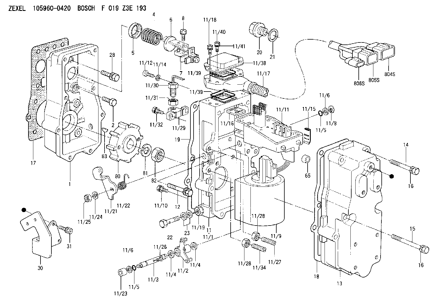
| 1. | [1] | 159560-1802 | GOVERNOR HOUSING |
| 2. | [10] | 139006-4100 | BLEEDER SCREW |
| 4. | [1] | 159635-8500 | COILED SPRING |
| 5. | [1] | 159564-4000 | SLOTTED WASHER |
| 6. | [1] | 159635-8800 | SLOTTED WASHER |
| 7. | [1] | 159636-3121 | CONNECTOR |
| 7B. | [1] | 159636-3321 | CONNECTOR |
| 7C. | [1] | 159636-3521 | CONNECTOR |
| 8. | [1] | 020105-1240 | BLEEDER SCREW M5P0.8L12 |
| 11. | [1] | 159620-7220 | ACTUATOR |
| 11/1. | [1] | 159562-3120 | PLATE;GOV. |
| 11/2. | [1] | 159583-1020 | STRAP |
| 11/3. | [1] | 159563-1700 | LEVER SHAFT |
| 11/4. | [2] | 029311-0170 | SHIM |
| 11/4. | [2] | 029311-0170 | SHIM |
| 11/5. | [2] | 159635-0200 | O-RING |
| 11/5. | [2] | 159635-0200 | O-RING |
| 11/6. | [2] | 014011-0140 | PLAIN WASHER D22&10.5T1.6 |
| 11/6. | [2] | 014011-0140 | PLAIN WASHER D22&10.5T1.6 |
| 11/8. | [1] | 016010-0940 | LOCKING WASHER |
| 11/9. | [1] | 159635-8621 | LINEAR DC MOTOR |
| 11/10. | [4] | 139006-9100 | BLEEDER SCREW |
| 11/11. | [1] | 407914-2000 | CONTROL UNIT |
| 11/12. | [4] | 010235-1640 | HEX-SOCKET-HEAD CAP SCREW |
| 11/12. | [4] | 010235-1640 | HEX-SOCKET-HEAD CAP SCREW |
| 11/14. | [4] | 029300-5020 | PLAIN WASHER D10&5.1T1.5 |
| 11/15. | [1] | 159636-0500 | LIP |
| 11/16. | [1] | 159635-9300 | GROMMET |
| 11/18. | [2] | 020105-1640 | BLEEDER SCREW M5P0.8L16 |
| 11/19. | [1] | 134002-0200 | ADAPTOR |
| 11/21. | [1] | 159583-6100 | CONTROL LEVER |
| 11/22. | [1] | 159563-4800 | COILED SPRING |
| 11/23. | [1] | 159563-1800 | BUSHING |
| 11/24. | [1] | 014110-8440 | LOCKING WASHER |
| 11/25. | [1] | 013030-8140 | UNION NUT M8P1.25H5 |
| 11/26. | [1] | 159563-1000 | FLAT-HEAD SCREW |
| 11/27. | [1] | 155615-1100 | FLAT-HEAD SCREW M6P1.0L37 |
| 11/28. | [2] | 029240-6010 | UNION NUT M6P1.0H5* |
| 11/28. | [2] | 029240-6010 | UNION NUT M6P1.0H5* |
| 11/29. | [1] | 159635-5400 | BRACKET |
| 11/30. | [1] | 479765-6820 | PULSE GENERATOR |
| 11/31. | [1] | 159635-0300 | UNION NUT |
| 11/32. | [2] | 020106-1440 | BLEEDER SCREW M6P1.0L14 |
| 11/34. | [1] | 159563-8400 | FLAT-HEAD SCREW |
| 11/38. | [1] | 159635-5520 | COVER |
| 11/39. | [2] | 159635-5200 | SEAL RING |
| 11/39. | [2] | 159635-5200 | SEAL RING |
| 11/40. | [4] | 159635-9800 | BLEEDER SCREW |
| 11/41. | [4] | 014110-6440 | LOCKING WASHER |
| 12. | [2] | 020106-4040 | BLEEDER SCREW |
| 13. | [1] | 159561-1300 | GOVERNOR COVER |
| 14. | [6] | 139006-1300 | BLEEDER SCREW M6P1L76 |
| 15. | [2] | 010006-5540 | BLEEDER SCREW M6P1L55 4T |
| 16. | [8] | 014110-6440 | LOCKING WASHER |
| 16. | [8] | 014110-6440 | LOCKING WASHER |
| 17. | [1] | 159566-4401 | GASKET |
| 18. | [1] | 159635-0100 | GASKET |
| 19. | [1] | 154390-0500 | GASKET |
| 20. | [1] | 153021-6300 | CAP |
| 21. | [1] | 139524-0000 | GASKET |
| 22. | [1] | 159564-0800 | EYE BOLT |
| 23. | [2] | 139514-0000 | GASKET D19.2&14.2T1.0 |
| 28. | [1] | 139008-1100 | BLEEDER SCREW |
| 30. | [1] | 159586-7920 | BRACKET |
| 31. | [3] | 020106-1440 | BLEEDER SCREW M6P1.0L14 |
| 65. | [2] | 159635-0400 | BUSHING |
| 80. | [1] | 159586-6400 | TOOTHED GEAR |
| 81. | [1] | 014111-2420 | LOCKING WASHER |
| 82. | [1] | 013031-2120 | UNION NUT |
| 83. | [1] | 025803-1310 | WOODRUFF KEY |
| 804S. | [1] | 159911-2300 | PLUG HOUSING |
| 805S. | [1] | 159911-2400 | PLUG HOUSING |
| 806S. | [1] | 159911-2500 | PLUG HOUSING |
Include in #1:
108622-1270
as GOVERNOR
Cross reference number
Zexel num
Bosch num
Firm num
Name
Information:
Illustration 1 g00565418
4W-8471 Time Delay Relay
Use a 6V-7070 Digital Multimeter, a stopwatch, and a battery (8 volts to 40 volts) for this test.
Connect the positive lead of the voltage source to terminal (TD-4) of the time delay relay. Connect the negative lead to terminal (TD-3). If the test is done on an engine, the start/stop switch must be in the STOP position in order to power terminal (TD-6). All connections must be maintained until the tests are completed.
Use the multimeter to determine continuity. Compare the measurements to the following table.
Table 1
Terminals Relay Position
5-6 Closed
6-7 Open
Connect the positive lead of the voltage source to terminal (TD-1). If the time delay relay is tested on the engine do not leave the voltage source hooked to terminal (TD-1) for more than 60 seconds. The fuel shutoff solenoid will be energized. Use the multimeter to determine continuity. Compare the measurements to the following table.
Table 2
Terminals Relay Position
5-6 Open
6-7 Closed
Remove the positive lead of the voltage source from terminal (TD-1). Use the stopwatch to measure the time that is needed for the position of the relay to change. Use the multimeter to determine continuity. Compare the measurements to the following table.
Table 3
Terminals Delay Time of Relay Position
0 to 60 seconds 80 seconds or more
5-6 Open Closed
6-7 Closed Open Note: If a jumper is normally installed across terminals (TD-2) and (TD-3), the jumper must be removed before performing Step 5.
Connect the positive lead of the voltage source to terminal (TD-2). If the time delay relay is tested on the engine, do not leave the voltage source on terminal (TD-2) for more than 60 seconds. The fuel shutoff solenoid will be energized. Use the stopwatch to measure the time that is needed for the position of the relay to change. Use the multimeter to determine continuity. Compare the measurements to the following table.
Table 4
Terminals Delay Time of Relay Position
0 to 8 seconds 10 seconds or more
5-6 Closed Open
6-7 Open Closed
Remove the positive lead of the voltage source from terminal (TD-1). Use the stopwatch to measure the time that is needed for the position of the relay to change. Use the multimeter to determine continuity. Compare the measurements to the following table.
Table 5
Terminals Delay Time of Relay Position
0 to 60 seconds 80 seconds or more
5-6 Open Closed
6-7 Closed Open
Remove the voltage source from terminal (TD-4). Use the multimeter to determine continuity. Compare the measurements to the following table.
Table 6
Terminals Relay Position
5-6 Closed
6-7 Open