Information electric governor
BOSCH
F 019 Z1E 980
f019z1e980
ZEXEL
105960-0252
1059600252
HINO
224002450A
224002450a
Rating:
Scheme ###:
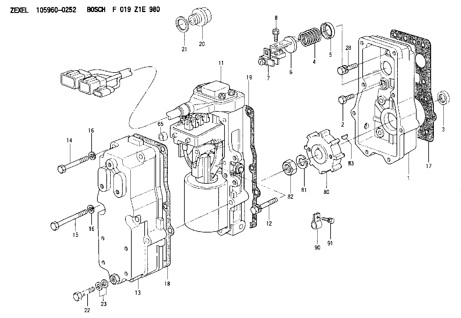
| 1. | [1] | 159560-1802 | GOVERNOR HOUSING |
| 2. | [10] | 139006-4100 | BLEEDER SCREW |
| 3. | [1] | 029621-7050 | PACKING RING |
| 4. | [1] | 159635-8500 | COILED SPRING |
| 5. | [1] | 159564-4000 | SLOTTED WASHER |
| 6. | [1] | 159564-4100 | SLOTTED WASHER |
| 7. | [1] | 159636-3120 | CONNECTOR 3.5MM |
| 7B. | [1] | 159636-3320 | CONNECTOR 4.0MM |
| 7C. | [1] | 159636-3520 | CONNECTOR 4.5MM |
| 8. | [1] | 020105-1240 | BLEEDER SCREW M5P0.8L12 |
| 11. | [1] | 159620-5021 | ACTUATOR |
| 12. | [2] | 020106-4040 | BLEEDER SCREW |
| 13. | [1] | 159561-1520 | GOVERNOR COVER |
| 14. | [6] | 139006-1300 | BLEEDER SCREW M6P1L76 |
| 15. | [2] | 010006-5540 | BLEEDER SCREW M6P1L55 4T |
| 16. | [8] | 014110-6440 | LOCKING WASHER |
| 16. | [8] | 014110-6440 | LOCKING WASHER |
| 17. | [1] | 159566-4401 | GASKET |
| 18. | [1] | 159635-0100 | GASKET |
| 19. | [1] | 154390-0500 | GASKET |
| 20. | [1] | 153021-6300 | CAP |
| 21. | [1] | 026524-3040 | GASKET |
| 22. | [1] | 029731-4680 | EYE BOLT |
| 23. | [2] | 139514-0300 | GASKET |
| 28. | [1] | 139008-1100 | BLEEDER SCREW |
| 65. | [2] | 159635-0400 | BUSHING |
| 80. | [1] | 159584-0800 | TOOTHED GEAR |
| 81. | [1] | 014111-2420 | LOCKING WASHER |
| 82. | [1] | 013031-2120 | UNION NUT |
| 83. | [1] | 025803-1310 | WOODRUFF KEY |
| 90. | [1] | 159586-4200 | CLAMPING BAND |
| 91. | [1] | 010010-1640 | BLEEDER SCREW M10P1.5L16 4T |
Cross reference number
Zexel num
Bosch num
Firm num
Name
105960-0252
F 019 Z1E 980
224002450A HINO
ELECTRIC GOVERNOR
K 14JE ELECTRIC GOVERNOR GOV
K 14JE ELECTRIC GOVERNOR GOV
Information:
Introduction
***#i00660713/i00660713*** contains the abbreviations, symbols, wiring sizes, wiring color and number codes for the ETR/ETS electric protection system which are placed on drawings and wiring, and referenced in the text of this Service Manual.The electrical system for the engine contains five subsystems. Each subsystem has different symbols and wire number codes. Abbreviations, symbols, numbering and lettering codes, and wiring requirements are described for the following subsystems.
Starting
Charging
Control
Monitoring
ProtectionThe engine electrical system is designed to improve operational reliability, reduce maintenance problems, improve the flexibility for making changes or additions to the system, and comply with international standards. In order to accomplish these goals, the engine electrical system contains the following components.
A steel junction box for the control, monitoring, and protection subsystems with standardized mounting locations on each engine series.
A steel power distribution box for the high amperage starting and charging subsystems with standardized mounting locations on each engine series.
A wiring harness in a protective nylon conduit that connects the junction box, power distribution box, and the electrical components located on the engine.
Common heat stamped wire number codes on each wire in the wiring harness for all engine models.
Common logic for all subsystems on all engine models."Description of Electrical System Symbols And Codes" explains how to use and understand the graphical representation of the ETR/ETS electric protection system by component and wiring abbreviations, symbols, and codes.Description of Electrical System Symbols And Codes
The Point-To-Point graphical system is used in all the wiring diagrams and schematics which help describe the systems operation and troubleshooting of the ETR/ETS electric protection system.Each wire in the wiring harness is heat stamped the length of the wire with the wire number code as shown in the ETR/ETS Wiring Using Wire Number Codes diagram on Illustration 7. The first number pair of the wiring code identifies the terminal on an engine component to which one end of the wire should be attached. The second number pair of the wiring code identifies the terminal on the component to which the other end of the wire should be attached. The number assigned to each terminal of each component will be the same for all engine models.The two numbers in the wiring code differentiate between left and right hand mounting. Illustration 2 contains the Number Codes and an example of usage.The symbols for the engine components will be the same for all 3200-3500 Series Engines.The use of abbreviations, symbols, and codes is provided by the following example. In order to locate and identify the wire which connects the starting motor magnetic switch and the starting motor, first determine the correct drawing abbreviation. The Abbreviation List on Illustration 1 shows ("SMMS") as the abbreviation symbol for the starting motor magnetic switch. ("SM") is shown as the abbreviation symbol for the starting motor. The symbols for both the starting motor magnetic switch and the starting motor are listed under the Starting System on 3.Locate the ("SMMS") and ("SM") symbols on the Starting System list on Illustration 3. Because an engine option exists for two
Have questions with 105960-0252?
Group cross 105960-0252 ZEXEL
Isuzu
Isuzu
Mitsubishi
Isuzu
Isuzu
Mitsubishi
Isuzu
Isuzu
Hino
105960-0252
F 019 Z1E 980
224002450A
ELECTRIC GOVERNOR