Information electric governor
BOSCH
F 019 Z3E 218
f019z3e218
ZEXEL
105960-0244
1059600244
ISUZU
1157900704
1157900704
Rating:
Scheme ###:
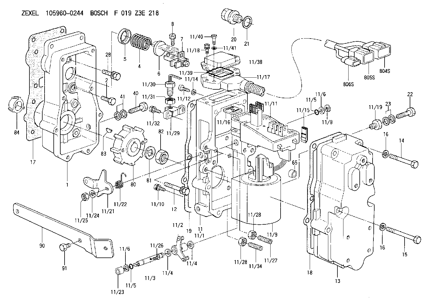
| 1. | [1] | 159560-3420 | GOVERNOR HOUSING |
| 2. | [10] | 139006-4100 | BLEEDER SCREW |
| 4. | [1] | 159635-8500 | COILED SPRING |
| 5. | [1] | 159564-4000 | SLOTTED WASHER |
| 6. | [1] | 159564-4100 | SLOTTED WASHER |
| 7. | [1] | 159636-3121 | CONNECTOR |
| 7B. | [1] | 159636-3321 | CONNECTOR |
| 7C. | [1] | 159636-3521 | CONNECTOR |
| 8. | [1] | 020105-1240 | BLEEDER SCREW M5P0.8L12 |
| 11. | [1] | 159620-4423 | ACTUATOR |
| 11/1. | [1] | 159562-2420 | PLATE;GOV. |
| 11/2. | [1] | 159583-1020 | STRAP |
| 11/3. | [1] | 159563-1700 | LEVER SHAFT |
| 11/4. | [2] | 029311-0170 | SHIM |
| 11/4. | [2] | 029311-0170 | SHIM |
| 11/5. | [2] | 159635-0200 | O-RING |
| 11/5. | [2] | 159635-0200 | O-RING |
| 11/6. | [2] | 014011-0140 | PLAIN WASHER D22&10.5T1.6 |
| 11/6. | [2] | 014011-0140 | PLAIN WASHER D22&10.5T1.6 |
| 11/8. | [1] | 016010-0940 | LOCKING WASHER |
| 11/9. | [1] | 159635-8621 | LINEAR DC MOTOR |
| 11/10. | [4] | 139006-9100 | BLEEDER SCREW |
| 11/11. | [1] | 407914-2000 | CONTROL UNIT |
| 11/12. | [4] | 010235-1640 | HEX-SOCKET-HEAD CAP SCREW |
| 11/14. | [4] | 029300-5020 | PLAIN WASHER D10&5.1T1.5 |
| 11/15. | [1] | 159636-0500 | LIP |
| 11/16. | [1] | 159635-9300 | GROMMET |
| 11/17. | [1] | 159630-3221 | CABLE SET |
| 11/18. | [2] | 020105-1640 | BLEEDER SCREW M5P0.8L16 |
| 11/19. | [1] | 134002-0200 | ADAPTOR |
| 11/21. | [1] | 159583-5220 | CONTROL LEVER |
| 11/22. | [1] | 159563-4800 | COILED SPRING |
| 11/23. | [1] | 159563-1800 | BUSHING |
| 11/24. | [1] | 014110-8440 | LOCKING WASHER |
| 11/25. | [1] | 013030-8140 | UNION NUT M8P1.25H5 |
| 11/26. | [1] | 159563-1000 | FLAT-HEAD SCREW |
| 11/27. | [1] | 155615-1100 | FLAT-HEAD SCREW M6P1.0L37 |
| 11/28. | [2] | 029240-6010 | UNION NUT M6P1.0H5* |
| 11/28. | [2] | 029240-6010 | UNION NUT M6P1.0H5* |
| 11/29. | [1] | 159635-5400 | BRACKET |
| 11/30. | [1] | 479765-6820 | PULSE GENERATOR |
| 11/31. | [1] | 159635-0300 | UNION NUT |
| 11/32. | [2] | 020106-1440 | BLEEDER SCREW M6P1.0L14 |
| 11/34. | [1] | 159563-8400 | FLAT-HEAD SCREW |
| 11/38. | [1] | 159635-5520 | COVER |
| 11/39. | [2] | 159635-5200 | SEAL RING |
| 11/40. | [4] | 159635-9800 | BLEEDER SCREW |
| 11/41. | [4] | 014110-6440 | LOCKING WASHER |
| 12. | [2] | 020106-4040 | BLEEDER SCREW |
| 13. | [1] | 159561-1300 | GOVERNOR COVER |
| 14. | [6] | 139006-1300 | BLEEDER SCREW M6P1L76 |
| 15. | [2] | 010006-5540 | BLEEDER SCREW M6P1L55 4T |
| 16. | [8] | 014110-6440 | LOCKING WASHER |
| 16. | [8] | 014110-6440 | LOCKING WASHER |
| 17. | [1] | 159566-4401 | GASKET |
| 18. | [1] | 159635-0100 | GASKET |
| 19. | [1] | 154390-0500 | GASKET |
| 20. | [1] | 153021-5000 | CAP |
| 21. | [1] | 026524-3040 | GASKET |
| 22. | [1] | 159636-0300 | EYE BOLT |
| 23. | [2] | 139514-0000 | GASKET D19.2&14.2T1.0 |
| 28. | [1] | 139008-1100 | BLEEDER SCREW |
| 40. | [1] | 159636-0300 | EYE BOLT |
| 41. | [2] | 139514-0000 | GASKET D19.2&14.2T1.0 |
| 65. | [2] | 159635-0400 | BUSHING |
| 80. | [1] | 159584-9900 | TOOTHED GEAR |
| 81. | [1] | 014111-2420 | LOCKING WASHER |
| 82. | [1] | 013031-2120 | UNION NUT |
| 83. | [1] | 025803-1310 | WOODRUFF KEY |
| 84. | [1] | 155412-5200 | IMPELLER WHEEL |
| 90. | [1] | 159586-4121 | BRACKET |
| 91. | [2] | 010010-1640 | BLEEDER SCREW M10P1.5L16 4T |
| 804S. | [1] | 159911-2300 | PLUG HOUSING |
| 805S. | [1] | 159911-2400 | PLUG HOUSING |
| 806S. | [1] | 159911-2500 | PLUG HOUSING |
Cross reference number
Zexel num
Bosch num
Firm num
Name
Information:
To avoid possible engine damage or another immediate shutdown, the water temperature fault must be corrected before attempting to restart the engine.
Even though the starter motor circuit can now be engaged, there is no fuel flow to the engine. The fuel flow to the engine is stopped until the coolant temperature falls below the rating for the water temperature contactor switch (WTS). When the coolant temperature falls below the rating for the water temperature contactor switch (WTS), the contactor switch opens again. The fuel shutoff solenoid is de-energized when the switch reopens. This allows fuel flow to the engine. The engine can then be restarted.When the coolant temperature decreases below the rating of the water temperature contactor switch, the switch opens again. The time delay relay also causes a delay of 70 seconds before the fuel shutoff solenoid (FSOS) is de-energized. The engine can then be restarted.
Accidental engine starting can cause injury or death to personnel working on the equipment.To avoid accidental engine starting, disconnect the battery cable from the negative (-) battery terminal. Completely tape all metal surfaces of the disconnected battery cable end in order to prevent contact with other metal surfaces which could activate the engine electrical system.Place a Do Not Operate tag at the Start/Stop switch location to inform personnel that the equipment is being worked on.
2301A Electric Governor Control
The 2301A Electric Governor Control activates all of the components that are in the electric protection system. The components are activated in the same manner when the nonelectric governor is used. One difference exists in the main circuit. The fuel shutoff solenoid (FSOS) (line 34) is not used.When the electric governor control is used, the engine must run in a normal condition in order for the electric circuit to operate in the manner that is described below.
Current flows from terminal (TS-28) (line 27) and current flows from terminal (TS-31) (line 35), which are located on the terminal strip in the junction box.
Current from terminals (TS-28) (line 27) and (TS-31) (line 35) flows through the preregulator (PR) (line 38) or the fuse (F4) to the electric governor control.
When the engine flywheel is rotating, the current also flows through the electric governor actuator (EGA) (line 52). When a fault in the system causes the current to energize the slave relay (SR1), the following events occur in the electric circuit in order to stop the engine.
The slave relay (SR1) opens across the contacts (SR1-30) and (SR1-87a) (line 45). The relay closes across the contacts (SR1-30) and (SR1-87) (line 43).
When the circuit opens across contacts (SR1-30) and (SR1-87a), the current is stopped to the electric governor control.
Current to the electric governor actuator (EGA) is also stopped.
The mechanical spring load in the electric governor actuator (EGA) will now move the fuel control rod in order to stop fuel flow to the engine.Note: With the exception of the differences that are described in this section of the manual, all of the fault circuits in the electric protection system are identical