Information electric governor
BOSCH
F 019 Z1E 931
f019z1e931
ZEXEL
105960-0202
1059600202
Rating:
Scheme ###:
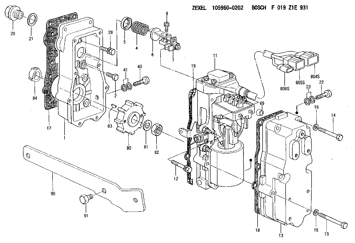
| 1. | [1] | 159560-3420 | GOVERNOR HOUSING |
| 2. | [10] | 139006-4100 | BLEEDER SCREW |
| 4. | [1] | 159635-8500 | COILED SPRING |
| 5. | [1] | 159564-4000 | SLOTTED WASHER |
| 6. | [1] | 159564-4100 | SLOTTED WASHER |
| 7. | [1] | 159636-3120 | CONNECTOR 3.5MM |
| 7B. | [1] | 159636-3320 | CONNECTOR 4.0MM |
| 7C. | [1] | 159636-3520 | CONNECTOR 4.5MM |
| 8. | [1] | 020105-1240 | BLEEDER SCREW M5P0.8L12 |
| 11. | [1] | 159620-4422 | ACTUATOR |
| 12. | [2] | 020106-4040 | BLEEDER SCREW |
| 13. | [1] | 159561-1300 | GOVERNOR COVER |
| 14. | [6] | 139006-1300 | BLEEDER SCREW M6P1L76 |
| 15. | [2] | 029010-6550 | BLEEDER SCREW |
| 16. | [8] | 014110-6440 | LOCKING WASHER |
| 16. | [8] | 014110-6440 | LOCKING WASHER |
| 17. | [1] | 159566-4401 | GASKET |
| 18. | [1] | 159635-0100 | GASKET |
| 19. | [1] | 154390-0500 | GASKET |
| 20. | [1] | 153021-5000 | CAP |
| 21. | [1] | 026524-3040 | GASKET |
| 22. | [1] | 159636-0300 | EYE BOLT |
| 23. | [2] | 139514-0000 | GASKET D19.2&14.2T1.0 |
| 28. | [1] | 139008-1100 | BLEEDER SCREW |
| 40. | [1] | 159636-0300 | EYE BOLT |
| 41. | [2] | 139514-0000 | GASKET D19.2&14.2T1.0 |
| 65. | [2] | 159635-0400 | BUSHING |
| 80. | [1] | 159586-0000 | TOOTHED GEAR |
| 81. | [1] | 014111-2420 | LOCKING WASHER |
| 82. | [1] | 013031-2120 | UNION NUT |
| 83. | [1] | 025803-1310 | WOODRUFF KEY |
| 84. | [1] | 155412-5200 | IMPELLER WHEEL |
| 90. | [1] | 159586-4121 | BRACKET |
| 91. | [2] | 010010-1640 | BLEEDER SCREW M10P1.5L16 4T |
| 804S. | [1] | 159911-2300 | PLUG HOUSING |
| 805S. | [1] | 159911-2400 | PLUG HOUSING |
| 806S. | [1] | 159911-2500 | PLUG HOUSING |
Include in #1:
108822-1022
as GOVERNOR
Cross reference number
Zexel num
Bosch num
Firm num
Name
Information:
TECHNICAL INFORMATION BULLETIN JAN. 15th, 2003
EXCAVATORS
WHEEL LOADERS
ENGINES 322C: (EMR, MAR);
325C: (CRB, CSJ, JLC, JLD, DTF)
950G II: (AYL, AYB);
962G II: (AYE, BAB)
3126B: (BMA)
Component Code(s) 1408SUBJECT: A NEW INJECTION ACTUATION PRESSURE CONTROL VALVE CONNECTOR INCREASES ENGINE OPERATION
PROBLEM:
The injection actuation pressure (IAP) control valve connector may have been assembled incorrectly on some 3126B engine harnesses. This can lead to intermittent engine operation or can cause the engine to stop.
SOLUTION:
If your machine exhibits symptoms of intermittent engine operation or abruptly stopping, the IAP control valve connector should be disconnected from the machine, examined for solenoid contact problems and re-installed using a correct procedure.
Procedure for installing the IAP control valve connector
This procedure will describe how to properly install the 232-4367 Harness.
Required Parts
Qty Part Number Description
1 232-4367 Harness
Procure the part that is listed in the table.
Illustration 1. Left Side of a 3126B Engine on a D6N.
(1) IAP Control Valve
(2) IAP Control Valve Connector
Note: Illustration 1 is from a D6N that is equipped with a 3126B for photographical purposes. The location of the IAP Control Valve is the same for your machine.
Disconnect the IAP control valve connector (2) from the IAP Control Valve (1). See Illustration 1.
Cut the two wires directly behind the connector.
Using wire strippers, strip the ends of the two wires.
Install the 232-4367 Harness, by crimping the stripped wires inside the splice.
Note: Take care to connect the pink wire to the pink wire on one hand and the purple wire to the purple wire on the other hand.
Heat both heat shrinkable tubes in order to insulate both the splices.
Reconnect the repaired harness to the IAP Control Valve (1).
COPYRIGHT 2003 CATERPILLAR
ALL RIGHTS RESERVED