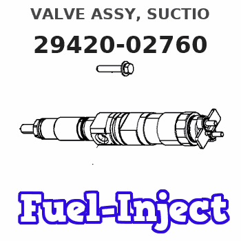
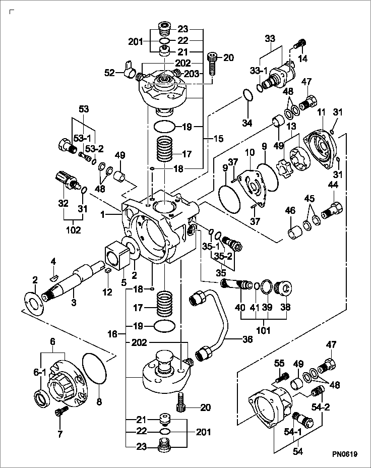
Information valve assy, suctio
Rating:
Compare Prices: .
As an associate, we earn commssions on qualifying purchases through the links below

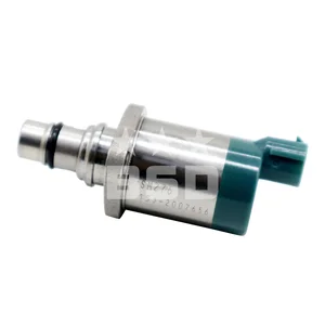
1pc 294200-2760, 294200-2750, 294200-4760, 1460A056
VNPOTTIQ
VNPOTTIQ


You can express buy:
USD 54.72
29-05-2025
29-05-2025
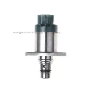
for Mitsubishi L200 car SCV valve metering unit control valve fuel metering unit solenoid valve 294200-2760 2942002760
USD 66.88
26-05-2025
26-05-2025
OEM 1460A056T 1460A056 294200-2760 Injection Pump Pressure Suction Control Valve SCV For MITSUBISHI L200 TRITON 2.5 DCI
USD 133.39
23-05-2025
23-05-2025
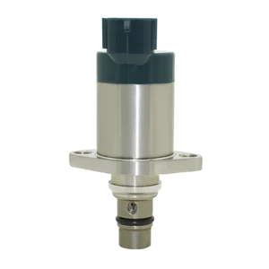
Suction Control Valve SCV OEM 294200-2760 294200-4760 1460A053 1460A056
Images:
USD 51.9

[19-May-2025]
USD 63.99

[19-May-2025]
USD 68.97

[19-May-2025]
USD 35.42

[19-May-2025]
Include in #3:
Cross reference number
| Part num | Firm num | Firm | Name |
| 29420-02760 | VALVE ASSY, SUCTIO |
Information:
start by:a) remove turbocharger1. Make a mark on compressor housing (1), cartridge assembly (3) and turbine housing for correct installation. 2. Loosen clamp assemblies (2). Remove compressor housing (1) and cartridge assembly (3) from the turbine housing.3. Put the cartridge assembly in tooling (A).
When nut (5) is loosened, do not put a side force on the shaft.
4. Remove nut (5) and O-ring seal (6). 5. Put the cartridge assembly in a press. Remove the shaft assembly from compressor wheel (7) and cartridge (8). 6. Remove seal ring (10) and shroud (11) from shaft assembly (9).7. Use tooling (B) to remove snap ring (12).
Do not cause damage to insert (13) when it is removed.
8. Install screwdrivers as shown. Carefully lift insert (13) out of the cartridge assembly. 9. Remove sleeve (14) and O-ring seal (15) from the insert. 10. Remove two seal rings (16) from the sleeve.11. Remove deflector (17) from the cartridge assembly. 12. Remove ring (18). 13. Remove sleeve (19) from the cartridge assembly. Make an identification of the position of bearing (20) for assembly purposes.14. Remove bearing (20) from the cartridge assembly. 15. Remove ring (21). 16. Use tooling (C) to remove snap ring (23). Remove sleeve (22) and the lower snap ring. 17. Turn the cartridge housing over. Remove snap ring (26) with tooling (C).18. Remove bearing (25), sleeve (24) and the lower snap ring. Assemble Turbocharger (Schwitzer 4TF555)
Make sure all of the oil passages in the turbocharger cartridge housing are clean and free of dirt and foreign material. Put clean engine oil on all parts of the cartridge assembly. 1. Install snap ring (4) with tooling (A) in cartridge housing (1).2. Put sleeve (3) and bearing (2) in position. Install snap ring (5) with tooling (A).3. Turn the cartridge housing over. Install snap ring (8) with tooling (A). 4. Install sleeve (6) and snap ring (7).5. Put ring (10) in position in the cartridge housing. 6. Install bearing (9) with grooved side up. Make an alignment of the dowel in the housing with the hole on the right side of the notch.7. Put sleeve (12) in position. Install ring (11). 8. Put deflector (13) in position as shown. 9. Put two seal rings (15) in position on sleeve (14).10. Put O-ring seal (17) in position on insert (16). 11. Install sleeve (14) in insert (16).12. Install insert assembly (18) with the flange down in the cartridge housing. 13. Put O-ring seal (20) in position.14. Install snap ring (19) with tooling (B). 15. Put shaft assembly (22) in tooling (D). Put 6V2055 High Vacuum Grease in the groove for seal ring (23) at assembly to one half or more of the depth of the groove all the way around the groove. 16. Put seal ring (23) in position on the shaft assembly.17. Install shround (21) on the shaft assembly (22).18. Lightly oil the wheel face that will be under the nut. Put compressor wheel (24) in position.
Do not put a side force on the shaft