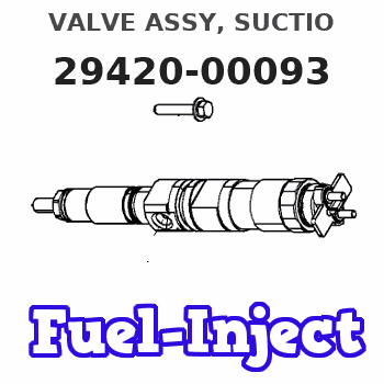
Information valve assy, suctio
Rating:
Compare Prices: .
As an associate, we earn commssions on qualifying purchases through the links below

1PC 04226-0L010 204200-0040 294200-0093 04226-30010 CQMLWSDNW
CQMLWSDNW
CQMLWSDNW
1PC 04226-0L010 204200-0040 294200-0093 04226-30010
RMZJOVHOW
RMZJOVHOW
You can express buy:
USD 40
14-06-2025
14-06-2025
DENSO SCV valve 042260L010 04226-0L010 294200-0040 294200-0093 FOR Hilux/Hiace 2DKFTV
USD 73.15
14-06-2025
14-06-2025
High Quality 294200-0093 Diesel Pump SCV Valve Solenoid Valve
USD 49
13-05-2025
13-05-2025
SCV 04226-0L010 Fuel Pump Suction Control Valve 294200-0040 22560-30020 294200-0093
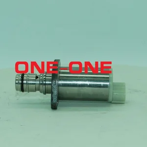
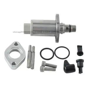
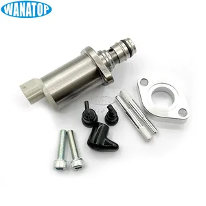
Images:
USD 24.49

[14-Jun-2025]
USD 48.64

[28-Apr-2025]
USD 362.06

[06-Jun-2025]
USD 58.8

[31-Aug-2022]
Include in #3:

Cross reference number
| Part num | Firm num | Firm | Name |
| 29420-00093 | SM | VALVE ASSY, SUCTIO |
Information:
Cleanliness
Whenever hydraulic, fuel, lubricating oil or air lines are disconnected, clean the point of disconnection and the adjacent area. As soon as the disconnection is made, cap, plug or tape the line or opening to prevent entry of foreign material. The same recommendations for cleaning and covering apply when access covers or inspection plates are removed.Clean and inspect all parts. Be sure all passages and holes are open. Cover all parts to keep them clean. Be sure parts are clean when installed. Leave new parts in their containers until ready for assembly.Removal And Installation
Unless otherwise specified, all removals should be accomplished using an adjustable lifting beam. All supporting members (chains and cables) should be parallel to each other and as near perpendicular as possible to the top of the object being lifted. When it is necessary to remove a component on an angle, remember that the capacity of an eyebolt diminishes as the angle between the supporting members and the object becomes less than 90°. Eyebolts and brackets should never be bent and should only have stress in tension. A length of pipe and a washer can be used, as shown, to help relieve these stresses on eyebolts.Forged eyebolts are available. Each size eyebolt has a maximum load recommendation.Some removals require the use of lifting fixtures to obtain proper balance and to provide safe handling.If a part resists removal, check to be certain all nuts and bolts have been removed and that an adjacent part is not interfering. Disassembly And Assembly
When assembling an engine, complete each step in turn. Do not partially assemble one part and start assembling some other part. Make all adjustments as recommended. Always check the job after it is completed to see nothing has been overlooked.Lubrication For A Rebuilt Engine
It is very important for a rebuilt engine to have "adequate" (needed) lubrication during the first seconds of operation. A "dry start" (without needed lubrication) on a rebuilt engine or an engine that has been in storage can cause bearing damage.To prevent the possibility of a "dry start" and bearing damage during the first seconds of running, use the 1P540 Flow Checking Tool Group and shop air pressure to pressure lubricate (fill the main oil passage with oil under pressure) all rebuilt engines and all engines that have been in storage.Procedure for Pressure Lubrication
1. Clean the tank of the 1P540 Flow Checking Tool Group thoroughly, and set the pressure regulator to 35 5 psi (240 35 kPa).
Air pressure should not be more than 50 psi (345 kPa) at any time.
2. Put engine oil in the tank. Use a minimum of 30% of the engine oil capacity. For some engines it will be necessary to fill the tank several times to get the correct amount of oil in the engine.3. Connect the tooling to the main oil passage of the engine.4. Add air pressure to the tank, with the regulator set at 35 5 psi (240 35 kPa). Although the tank does