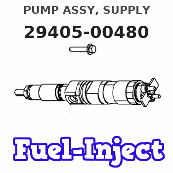
Information pump assy, supply
Rating:
Compare Prices: .
As an associate, we earn commssions on qualifying purchases through the links below

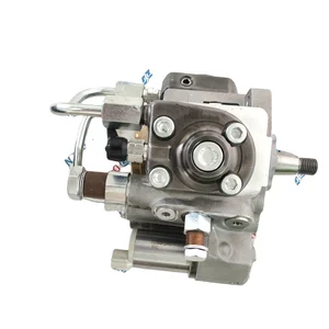
Fuel Injection Pump SE502553 RE543262 Fits for JD Engine 6.8L 6068 Excavator 210G 210GLC 250GLC 290GLC 350GLC 380GLC
ZJSYPXB ⚙️ Part Name ⚙️:Fuel Injection Pump || ⚙️ Part Number ⚙️:SE502553 RE543262 || ⚙️ Application ⚙️:Compatible with JD Engine 6.8L 6068 Excavator 210G 210GLC 250GLC 290GLC 350GLC 380GLC || ⚙️ Accurate ⚙️ -Install and use our accessories. Please find the right product according to the old part number and machine model, if you are not sure, please contact us in time, we are more than happy to provide services || ⚙️ Reliable performance ⚙️ -Carefully designed and tested, with high reliability and stability, can maintain good working condition for a long time.
ZJSYPXB ⚙️ Part Name ⚙️:Fuel Injection Pump || ⚙️ Part Number ⚙️:SE502553 RE543262 || ⚙️ Application ⚙️:Compatible with JD Engine 6.8L 6068 Excavator 210G 210GLC 250GLC 290GLC 350GLC 380GLC || ⚙️ Accurate ⚙️ -Install and use our accessories. Please find the right product according to the old part number and machine model, if you are not sure, please contact us in time, we are more than happy to provide services || ⚙️ Reliable performance ⚙️ -Carefully designed and tested, with high reliability and stability, can maintain good working condition for a long time.

Fuel Pump RE543262 for John Deere Engine 6.8L 6068 Excavator 210G 250GLC 290GLC
EPISTA part number:RE543262 || applications:for John Deere Engine 6.8L 6068 Excavator 210G 250GLC 290GLC
EPISTA part number:RE543262 || applications:for John Deere Engine 6.8L 6068 Excavator 210G 250GLC 290GLC

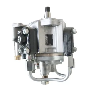
Tenlioshun Fuel Injection Pump RE543262 SE502553 Compatible with John Deere Engine 6.8L 6068 Excavator 210G 210GLC 250GLC 290GLC 350GLC 380GLC
Tenlioshun Note: When ordering, please check the picture and part number, the picture is taken in real life || Compatible with John Deere Engine 6.8L 6068 Excavator 210G 210GLC 250GLC 290GLC 350GLC 380GLC || Warranty: 6 Months || Product Name: Fuel Injection Pump || Part number: RE543262 SE502553
Tenlioshun Note: When ordering, please check the picture and part number, the picture is taken in real life || Compatible with John Deere Engine 6.8L 6068 Excavator 210G 210GLC 250GLC 290GLC 350GLC 380GLC || Warranty: 6 Months || Product Name: Fuel Injection Pump || Part number: RE543262 SE502553
You can express buy:
USD 653.71
14-06-2025
14-06-2025
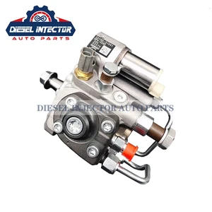
Fuel · Pump RE543262 294050-0480 Compatible with John De ere Engine 6.8L 6068
USD 421.66
14-06-2025
14-06-2025
New Diesel injection fuel injector pump 294050-0480 RE543262 For JOHN DEERE S450
USD 461.01
01-06-2025
01-06-2025
Good new HP3 fuel pump 294050-0480 2940500480 for s450 engine
Images:
USD 381.42

[15-May-2025]
USD 393.14

[13-May-2025]
USD 393.14

[13-May-2025]
USD 428.04

[19-May-2025]
Components :
| 001. | PUMP ASSY, SUPPLY | 29405-00480 |
| 002. | OVERHAUL KIT, SUPP | 29400-90051 |
Scheme ###:
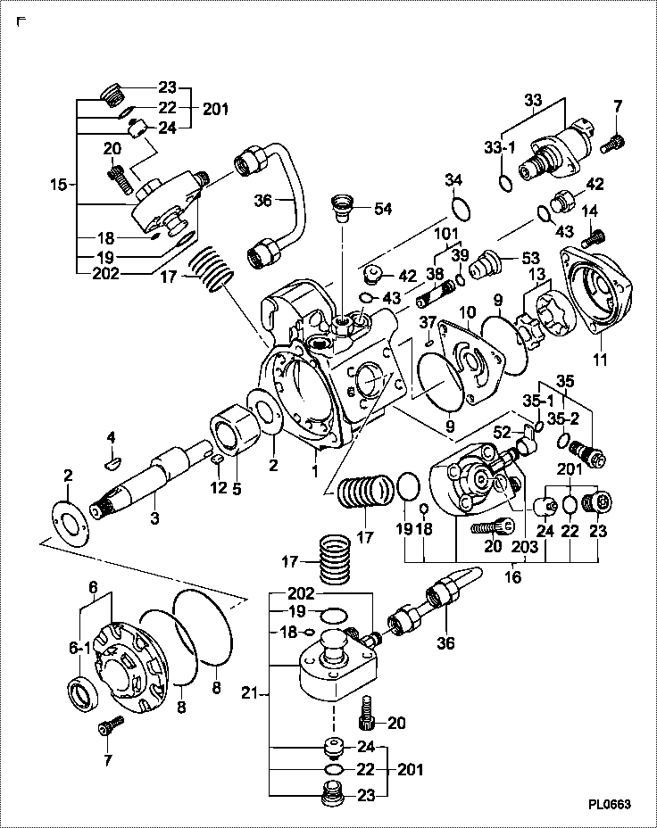
| 000. | [01] | 29405-00480 | PUMP ASSY, SUPPLY | RE543262 |
| 001. | [01] | 29410-05550 | HOUSING SUB-ASSY, | |
| 002. | [02] | 29417-80040 | WASHER, CAMSHAFT | |
| 003. | [01] | 29419-15080 | CAMSHAFT, SUPPLY P | |
| 004. | [01] | 29402-10040 | KEY, WOODRUFF | |
| 005. | [01] | 29417-05011 | RING SUB-ASSY, CAM | |
| 005. | [01] | 29417-05020 | RING SUB-ASSY, CAM | |
| 006. | [01] | 29412-05050 | COVER SUB-ASSY, BE | |
| 006-001. | [01] | 29419-70010 | SEAL, OIL | |
| 007. | [08] | 09644-90110 | BOLT, SOCKET | |
| 008. | [02] | 29419-80050 | O-RING, SUPPLY PUM | |
| 009. | [02] | 29419-80030 | O-RING, SUPPLY PUM | |
| 010. | [01] | 29418-35020 | PLATE, FEED PUMP, | |
| 011. | [01] | 29418-45040 | COVER, FEED PUMP | |
| 012. | [01] | 29418-70040 | KEY, FEED PUMP | |
| 013. | [01] | 29418-00080 | ROTOR SET, FEED PU | |
| 014. | [03] | 09644-90050 | BOLT, SOCKET | |
| 015. | [01] | 29409-00590 | ELEMENT KIT, SUPPL | |
| 016. | [01] | 29409-00600 | ELEMENT KIT, SUPPL | |
| 017. | [03] | 29415-90040 | SPRING, PLUNGER | |
| 018. | [03] | 29419-80010 | O-RING, SUPPLY PUM | |
| 019. | [03] | 29419-80040 | O-RING, SUPPLY PUM | |
| 020. | [12] | 29419-90010 | BOLT, SOCKET | |
| 021. | [01] | 29409-00610 | ELEMENT KIT, SUPPL | |
| 033. | [01] | 29420-00880 | VALVE ASSY, SUCTIO | |
| 033-001. | [01] | 29428-60010 | O-RING, VALVE | |
| 034. | [01] | 29428-50010 | O-RING, SOLENOID | |
| 035. | [01] | 29416-00200 | VALVE SUB-ASSY, RE | |
| 035-001. | [01] | 29419-80060 | O-RING, SUPPLY PUM | |
| 035-002. | [01] | 29419-80070 | O-RING, SUPPLY PUM | |
| 036. | [02] | 29401-05100 | PIPE, SUPPLY PUMP | |
| 037. | [02] | 29416-90010 | PIN, STOPPER | |
| 038. | [01] | 09737-00040 | FILTER SUB-ASSY | |
| 039. | [01] | 29419-80180 | O-RING, SUPPLY PUM | |
| 042. | [02] | 09031-70510 | PLUG, SCREW | |
| 043. | [02] | 09806-50020 | GASKET | |
| 052. | [01] | 09001-40160 | CAP, VALVE HOLDER | |
| 053. | [01] | 09003-45220 | PLUG | |
| 054. | [01] | 09003-45230 | PLUG | |
| 101. | [01] | 29400-90070 | OVERHAUL KIT, SUPP | RE524528 |
| 200. | [01] | 29400-90051 | OVERHAUL KIT, SUPP |
Include in #3:
29405-00480
as PUMP ASSY, SUPPLY
Cross reference number
| Part num | Firm num | Firm | Name |
| 29405-00480 | RE543262 | PUMP ASSY, SUPPLY | |
| RE543262 | JOHN DEERE | PUMP ASSY, SUPPLY |
Information:
Start By:a. remove rocker arm assemblies and push rods1. Disconnect the governor control linkage. See the 3114 & 3116 Engines Governor Service Manual, Form No. SENR6454.
Do not move the fuel control linkage or the injector racks with out the Injector Compressors [Tool (A)] installed. Damage to the fuel injectors can result. After installation of Tool (A), tap on the top of each fuel injector lightly with a rubber mallet to prevent any binding or side loading in the fuel injectors.
2. When removing the fuel control linkage with the fuel injectors in place, install Tool (A) on the fuel injectors, and slightly compress the injector springs.3. Remove four bolts (1) and fuel control linkage (2). The following steps are for the installation of the fuel control linkage.4. Be sure the two screws in each inboard bracket are loose.5. Put fuel control linkage in position on the cylinder head assembly. Be sure all injector racks are engaged and the small dowel in each mounting bracket is in the proper position before tightening bolts (1). Install four bolts (1), and tighten them as follows: a. Tighten the two outer bearing bracket mounting bolts.b. Tighten the inner bearing bracket(s) mounting bolt(s).c. Position the inner bearing(s) to allow free rotation of the rack control rod.d. Tighten the two screws in on each inner bracket(s) to a torque of 3.5 0.2 N m (31 2 lb in).e. The control rod must rotate when a force of 4.4 N (1 lb) or less is applied to control lever (3) in the direction indicated by arrows.6. Connect the governor control linkage. See the 3114 & 3116 Engines Governor Service Manual, Form No. SENR6454.7. After installation of the rocker arm assemblies and push rods, Check and/or adjust the following: Injector Synchronization, Fuel Setting, Fuel Timing, Valve Lash. See the 3114 & 3116 Diesel Truck Engines Systems Operation Testing & Adjusting module, Form No. SENR6437 to check and/or adjust the above items.End By:a. install rocker arm assemblies and push rods