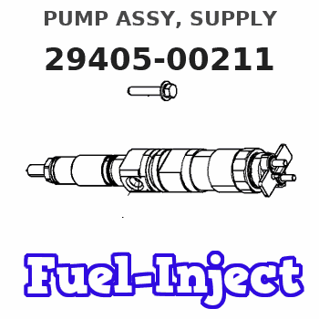
Information pump assy, supply
Rating:
You can express buy:
USD 202
16-03-2019
16-03-2019
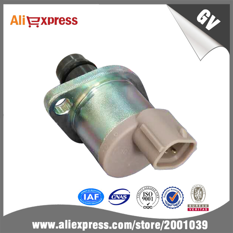
Fuel pump suction control valve 294200-0190 scv valve 294200-0190 for fuel pump 294050-0081 294050-0211
Components :
| 001. | PUMP ASSY, SUPPLY | 29405-00211 |
| 002. | OVERHAUL KIT, SUPP | 29400-90051 |
Scheme ###:
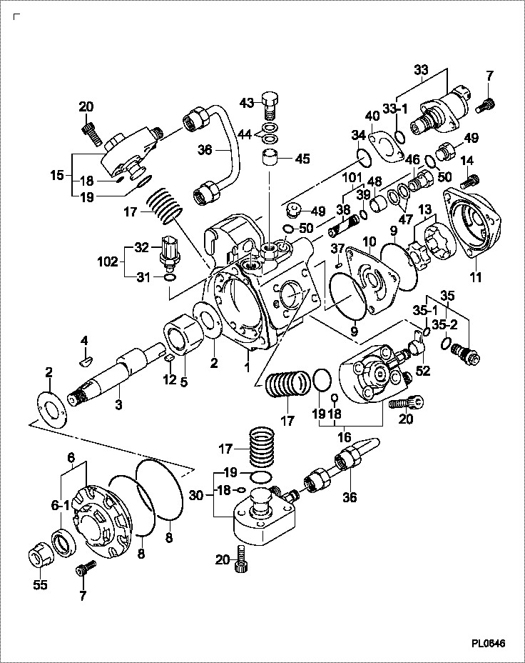
| 000. | [01] | 29405-00212 | PUMP ASSY, SUPPLY | |
| 001. | [01] | 29410-05120 | HOUSING SUB-ASSY, | |
| 001. | [01] | 29410-05330 | HOUSING SUB-ASSY, | |
| 001. | [01] | 29410-05820 | HOUSING SUB-ASSY, | |
| 002. | [02] | 29417-80040 | WASHER, CAMSHAFT | |
| 003. | [01] | 29419-15090 | CAMSHAFT, SUPPLY P | |
| 003. | [01] | 29419-15060 | CAMSHAFT, SUPPLY P | |
| 003. | [01] | 29419-15030 | CAMSHAFT, SUPPLY P | |
| 003. | [01] | 29419-15010 | CAMSHAFT, SUPPLY P | |
| 004. | [01] | 29402-10020 | KEY, WOODRUFF | 3313345700 |
| 004. | [01] | 29402-10040 | KEY, WOODRUFF | |
| 005. | [01] | 29417-05000 | RING SUB-ASSY, CAM | |
| 005. | [01] | 29417-05011 | RING SUB-ASSY, CAM | |
| 006. | [01] | 29412-05030 | COVER SUB-ASSY, BE | |
| 006. | [01] | 29412-05070 | COVER SUB-ASSY, BE | |
| 006. | [01] | 29412-05050 | COVER SUB-ASSY, BE | |
| 006-001. | [01] | 29419-70010 | SEAL, OIL | |
| 007. | [08] | 09644-90110 | BOLT, SOCKET | |
| 007. | [06] | 09644-90110 | BOLT, SOCKET | |
| 008. | [02] | 29419-80050 | O-RING, SUPPLY PUM | |
| 009. | [02] | 29419-80030 | O-RING, SUPPLY PUM | |
| 010. | [01] | 29418-35030 | PLATE, FEED PUMP, | |
| 011. | [01] | 29418-45010 | COVER, FEED PUMP | |
| 012. | [01] | 29418-70010 | KEY, FEED PUMP | |
| 012. | [01] | 29418-70040 | KEY, FEED PUMP | |
| 013. | [01] | 29418-00080 | ROTOR SET, FEED PU | |
| 014. | [03] | 09644-90050 | BOLT, SOCKET | |
| 014. | [05] | 09644-90050 | BOLT, SOCKET | |
| 015. | [01] | 29409-00230 | ELEMENT KIT, SUPPL | |
| 015. | [01] | 29409-00870 | ELEMENT KIT, SUPPL | |
| 016. | [01] | 29409-00240 | ELEMENT KIT, SUPPL | |
| 016. | [01] | 29409-00880 | ELEMENT KIT, SUPPL | |
| 017. | [03] | 29415-90040 | SPRING, PLUNGER | |
| 018. | [03] | 29419-80010 | O-RING, SUPPLY PUM | |
| 019. | [03] | 29419-80040 | O-RING, SUPPLY PUM | |
| 020. | [12] | 29419-90010 | BOLT, SOCKET | |
| 030. | [01] | 29409-00250 | ELEMENT KIT, SUPPL | |
| 030. | [01] | 29409-00890 | ELEMENT KIT, SUPPL | |
| 031. | [01] | 09806-60030 | O-RING, DISTRIBUTI | |
| 032. | [01] | 17973-00020 | SENSOR, FUEL TEMPE | |
| 032. | [01] | 17973-00100 | SENSOR, FUEL TEMPE | |
| 033. | [01] | 29420-00670 | VALVE ASSY, SUCTIO | |
| 033. | [01] | 29420-00190 | VALVE ASSY, SUCTIO | |
| 033-001. | [01] | 29428-60030 | O-RING, VALVE | |
| 034. | [01] | 29428-50040 | O-RING, SOLENOID | |
| 034. | [01] | 29428-50010 | O-RING, SOLENOID | |
| 035. | [01] | 29416-00011 | VALVE SUB-ASSY, RE | |
| 035-001. | [01] | 29419-80060 | O-RING, SUPPLY PUM | |
| 035-002. | [01] | 29419-80070 | O-RING, SUPPLY PUM | |
| 036. | [02] | 29401-05060 | PIPE, SUPPLY PUMP | |
| 036. | [02] | 29401-05030 | PIPE, SUPPLY PUMP | |
| 037. | [02] | 29416-90010 | PIN, STOPPER | |
| 038. | [01] | 09737-00040 | FILTER SUB-ASSY | |
| 039. | [01] | 29419-80180 | O-RING, SUPPLY PUM | |
| 040. | [01] | 29425-90020 | GASKET, SOLENOID | |
| 043. | [01] | 09543-80010 | SCREW, HOLLOW | 3313745700 |
| 043. | [01] | 09543-80170 | SCREW, HOLLOW | |
| 044. | [02] | 94901-02530 | WASHER | |
| 045. | [01] | 29409-90010 | COLLAR, FUEL OUTLE | |
| 046. | [01] | 94918-00310 | SCREW, HOLLOW | 3313645700 |
| 047. | [02] | 94901-02490 | WASHER | |
| 048. | [01] | 94919-80270 | COLLAR, PRESSBOARD | |
| 049. | [02] | 09031-70060 | PLUG, SCREW | |
| 050. | [02] | 09806-50020 | GASKET | |
| 101. | [01] | 29400-90070 | OVERHAUL KIT, SUPP | |
| 102. | [01] | 29400-90020 | OVERHAUL KIT, SUPP | |
| 200. | [01] | 29400-90051 | OVERHAUL KIT, SUPP |
Cross reference number
| Part num | Firm num | Firm | Name |
| 29405-00211 | PUMP ASSY, SUPPLY |
Information:
Start By:a. remove valve cover 1. Remove four bolts (1) that hold each rocker arm assembly in position. Remove the rocker arm assemblies from the engine.2. Put identification marks on all push rods as to their location in the engine. Remove the push rods from the engine. 3. Disassemble the rocker arm assemblies as follows: a. Remove the pin and rocker arm mounts (2). Remove the two rocker arm assemblies and the unit injector arm assembly from the shaft assembly.b. Remove the nut and valve adjusting screw (3) from each rocker arm.c. Remove arm button (7), retaining ring (6) and the arm socket from the unit injector arm.d. Loosen the nut, and remove injection adjusting screw (4) from the unit injector arm.e. Remove sleeve bearing (5) from the unit injector arm. The following steps are for the installation of the rocker arm assemblies and push rods.4. Be sure all parts of the rocker arm assemblies are clean.5. Assemble the rocker arm assemblies as follows: a. Install sleeve bearing (5) in the unit injector arm with Tool (A).b. Install injection adjusting screw (4) and the nut in the unit injector arm.c. Install the arm socket, retaining ring (6) and arm button (7) in the unit injector arm.d. Install valve adjusting screw (3) and the nut in each rocker arm.e. Put the rocker arm assemblies and the unit injector arm assembly in position on the shaft assembly. Install two rocker arm mounts (2) and the pins that hold them.6. Apply clean engine oil to the push rods, and install them in their original locations in the engine. Be sure the push rods are seated in the lifter arm assemblies.7. Loosen all adjusting screws in the rocker arm assemblies. Position the rocker arm assemblies on the cylinder head assembly, and install bolts (1) that hold them in position.8. Adjust the fuel timing and the valve lash. See the topics "Fuel Timing" & "Valve Lash" in the 3114 & 3116 Diesel truck Engines Systems Operation & Testing & Adjusting module, Form No. SENR6437.End By:a. install valve cover