Information overhaul kit, supp
Rating:
Scheme ###:
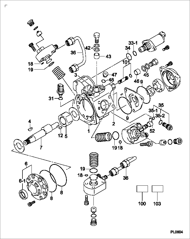
| 000. | [01] | 29400-90840 | OVERHAUL KIT, SUPP | |
| 001. | [01] | 29410-05042 | HOUSING SUB-ASSY, | |
| 001. | [01] | 29410-05561 | HOUSING SUB-ASSY, | |
| 002. | [01] | 29403-10020 | UNION | |
| 003. | [01] | 29403-10040 | UNION | |
| 004. | [01] | 29402-10020 | KEY, WOODRUFF | |
| 004. | [01] | 29402-10040 | KEY, WOODRUFF | |
| 005. | [01] | 29417-05011 | RING SUB-ASSY, CAM | |
| 006. | [01] | 29412-05050 | COVER SUB-ASSY, BE | |
| 006. | [01] | 29412-05070 | COVER SUB-ASSY, BE | |
| 006-001. | [01] | 29419-70010 | SEAL, OIL | |
| 007. | [01] | 29419-15090 | CAMSHAFT, SUPPLY P | |
| 008. | [02] | 29419-80050 | O-RING, SUPPLY PUM | |
| 009. | [02] | 29419-80030 | O-RING, SUPPLY PUM | |
| 012. | [01] | 29418-70010 | KEY, FEED PUMP | |
| 012. | [01] | 29418-70040 | KEY, FEED PUMP | |
| 018. | [03] | 29419-80010 | O-RING, SUPPLY PUM | |
| 019. | [03] | 29419-80040 | O-RING, SUPPLY PUM | |
| 031. | [01] | 09806-60030 | O-RING, DISTRIBUTI | |
| 033-001. | [01] | 29428-60010 | O-RING, VALVE | |
| 034. | [01] | 29428-50010 | O-RING, SOLENOID | |
| 035. | [01] | 29416-00011 | VALVE SUB-ASSY, RE | |
| 035. | [01] | 29416-00200 | VALVE SUB-ASSY, RE | |
| 035-001. | [01] | 29419-80060 | O-RING, SUPPLY PUM | |
| 035-002. | [01] | 29419-80070 | O-RING, SUPPLY PUM | |
| 036. | [02] | 29401-05010 | PIPE, SUPPLY PUMP | |
| 042. | [02] | 94901-02530 | WASHER | ME743814 |
| 043. | [01] | 94919-80260 | COLLAR, PRESSBOARD | ME702848 |
| 045. | [02] | 94901-02490 | WASHER | ME743859 |
| 046. | [01] | 94919-80270 | COLLAR, PRESSBOARD | ME702632 |
| 047. | [01] | 09031-70060 | PLUG, SCREW | ME702176 |
| 048. | [01] | 09806-50020 | GASKET | |
| 052. | [01] | 09001-40160 | CAP, VALVE HOLDER | |
| 100. | [01] | 29400-90880 | OVERHAUL KIT, SUPP | |
| 101. | [01] | 29400-90070 | OVERHAUL KIT, SUPP | |
| 103. | [01] | 29405-39002 | NAMEPLATE |
Include in #3:
29400-90840
as OVERHAUL KIT, SUPP
Cross reference number
| Part num | Firm num | Firm | Name |
| 29400-90840 | OVERHAUL KIT, SUPP |
Information:
1. Remove bolts (1) that hold main bearing caps (2) to the block, and remove main bearing caps (2). 2. Install one of the bolts from the front pulley in each end of the crankshaft.3. Fasten a hoist to crankshaft (3), and remove crankshaft (3) from the block. The weight is 159 kg (350 lb.). If new main bearings are not to be installed, keep old bearings with identification as to their location in cylinder block. 4. Use tooling (A) to remove the crankshaft gear.5. Use tooling (B) if necessary to remove the dowel and the pin.Install Crankshaft
If the crankshaft journals and bores for the block and rods were measured at disassembly and found to be within specifications, no further checks are necessary. However, if the serviceman still wants to measure the bearing clearances, Plastigage is recommended. Lead wire, shim stock or use of a dial bore gauge can damage the bearing surface.The serviceman must be very careful to use Plastigage, tool (B) correctly. The following points must be remembered:... Make sure that the backs of the bearings and the bores are clean and dry.... Make sure that the bearing locking tabs are properly seated in their slots.... The crankshaft must be free of oil where the Plastigage touches it.... If the main bearing clearances are checked with the engine upright or on its side, the crankshaft must be supported. Use a jack under an adjacent crankshaft counterweight and hold the crankshaft against the crown of the bearing. If the crankshaft is not supported, the weight of the crankshaft will cause incorrect readings.... Put a piece of Plastigage on the crown of the bearing half that is in the cap. Do not allow the Plastigage to extend over the edge of the bearing.... Install the bearing cap using the correct torque-turn specifications. Do not use an impact wrench. Be careful not to dislodge the bearing when the cap is installed.... Do not turn the crankshaft with the Plastigage installed.... Carefully remove the cap but do not remove the Plastigage. Measure the width of the Plastigage while it is in the bearing cap or on the crankshaft journal. Do this by using the correct scale on the package. Record the measurements.... Remove the Plastigage before reinstalling the cap.When using Plastigage, the readings can sometimes be unclear. For example, all parts of the Plastigage are not the same width. Measure the major widths to make sure that they are within the specification range. Also, experience has shown that when checking clearances tighter than 0.10 mm (.004 in.) the readings may be low by 0.013 to 0.025 mm (.0005 to .0010 in.). Out-of-round journals can give faulty readings. Also, journal taper may be indicated when one end of the Plastigage is wider that the other.For complete details concerning measuring bearing clearances, see Engine Bearings And Crankshafts, Form No. SEBD0531. 1. Install pin (5) in the crankshaft end until it is extended from the surface 6.4 0.5 mm (.25 .02
If the crankshaft journals and bores for the block and rods were measured at disassembly and found to be within specifications, no further checks are necessary. However, if the serviceman still wants to measure the bearing clearances, Plastigage is recommended. Lead wire, shim stock or use of a dial bore gauge can damage the bearing surface.The serviceman must be very careful to use Plastigage, tool (B) correctly. The following points must be remembered:... Make sure that the backs of the bearings and the bores are clean and dry.... Make sure that the bearing locking tabs are properly seated in their slots.... The crankshaft must be free of oil where the Plastigage touches it.... If the main bearing clearances are checked with the engine upright or on its side, the crankshaft must be supported. Use a jack under an adjacent crankshaft counterweight and hold the crankshaft against the crown of the bearing. If the crankshaft is not supported, the weight of the crankshaft will cause incorrect readings.... Put a piece of Plastigage on the crown of the bearing half that is in the cap. Do not allow the Plastigage to extend over the edge of the bearing.... Install the bearing cap using the correct torque-turn specifications. Do not use an impact wrench. Be careful not to dislodge the bearing when the cap is installed.... Do not turn the crankshaft with the Plastigage installed.... Carefully remove the cap but do not remove the Plastigage. Measure the width of the Plastigage while it is in the bearing cap or on the crankshaft journal. Do this by using the correct scale on the package. Record the measurements.... Remove the Plastigage before reinstalling the cap.When using Plastigage, the readings can sometimes be unclear. For example, all parts of the Plastigage are not the same width. Measure the major widths to make sure that they are within the specification range. Also, experience has shown that when checking clearances tighter than 0.10 mm (.004 in.) the readings may be low by 0.013 to 0.025 mm (.0005 to .0010 in.). Out-of-round journals can give faulty readings. Also, journal taper may be indicated when one end of the Plastigage is wider that the other.For complete details concerning measuring bearing clearances, see Engine Bearings And Crankshafts, Form No. SEBD0531. 1. Install pin (5) in the crankshaft end until it is extended from the surface 6.4 0.5 mm (.25 .02